Cấu hình HA Juniper SRX340 Router

Trước khi bắt đầu cấu hình cluster, hãy xóa hết cấu hình hiện có để tránh lỗi phát sinh  trong quá trình cấu hình cluster. Trong mỗi thiết bị srx thực hiện các bước sau:

Đầu tiên, hãy xóa tất cả các logical interface dùng cho control link/plane(ge-0/0/1) & Data/fabric link/plane(ge-0/0/2). 

***Note: Control link và Data link khác nhau ở mỗi model SRX

delete system host-namedelete vlans delete interfaces vlan delete security delete interfaces ge-0/0/1 delete interfaces ge-0/0/2 delete interfaces ge-0/0/3 unit 0 family ethernet-switching delete interfaces ge-0/0/4 unit 0 family ethernet-switching

Sau khi xoá kiểm tra và chắc chắn rằng  không còn ethernet-switching nào 

root@srx1# show | match ethernet-switching | count
Count: 0 lines
[edit]
root@srx1#

Sau đó, kết nối vật lý hai thiết bị và đảm bảo rằng chúng là cùng một loại. 

Ví dụ, trên SRX340 kết nối cổng control ports trên node 0 và node 1.

***Lưu ý: Đối với các thiết bị SRX300, SRX320, SRX340 và SRX345, hãy kết nối ge-0/0/1 trên node 0 với ge-0/0/1 trên node 1.

1. Cấu hinh hai thiết bị ở chế độ cluster và khởi động lại. Việc cấu hình được thực hiện trên cả hai thiết bị

On node 0:
---------------
user@host> set chassis cluster cluster-id 1 node 0 reboot

On node 1:
---------------
user@host> set chassis cluster cluster-id 1 node 1 reboot

Sau khi khởi động lại kiểm tra tại dấu nhắc của srx1 node0, bạn sẽ thấy dấu nhắc thay đổi như bên dưới: 

{hold:node0}
root@srx1>
{secondary:node0}
root@srx1>
{primary:node0}
root@srx1>

Kiểm tra tình trạng cluster

root@srx1> show chassis cluster status
Cluster ID: 1
Node                  Priority          Status    Preempt  Manual failover

Redundancy group: 0 , Failover count: 1
    node0                   1           primary        no       no
    node1                   1           secondary      no       no

Sau khi cluster được thiết lập, đối với thiết bị SRX340 interface ge-0/0/1 trên node 1 sẽ chuyển thành ge-5/0/1.

 2. Cấu hình tên thiết bị và địa chỉ IP quản lý cho mỗi thiết bị, việc cấu hình chỉ thực hiện trên node đầu tiên (srx-node0)

set groups node0 system host-name srx-nd0
set groups node0 interfaces fxp0 unit 0 family inet address 192.168.33.1/24
set groups node1 system host-name srx-nd1
set groups node1 interfaces fxp0 unit 0 family inet address 192.168.33.2/24

3. Cấu hình ‘apply-groups’

set apply-groups "${node}"

4. Định nghĩa các interfaces được sử dụng cho kết nối fab (data plane links for RTO sync) bằng cách sử dụng các interfaces ge-0/0/2 từ mỗi node. Việc cấu hình các liên kết fabric chỉ thực hiện trên node đầu tiên (srx-node0)

set interfaces fab0 fabric-options member-interfaces  ge-0/0/2
set interfaces fab1 fabric-options member-interfaces  ge-5/0/2

# Sau khi commit, cấu hình cũng sẽ đồng bộ vào node srx-node1. Bây giờ hãy kiểm tra cluster interfaces status 

root@srx1> show chassis cluster interfaces
Control link 0 name: fxp1
Control link status: Up

Fabric interfaces:
Name    Child-interface    Status
fab0       fe-0/0/5          up
fab0
fab1       fe-2/0/5          up
fab1
Fabric link status: Up

5. Thiết lập redundancy group 0 cho Routing Engine failover properties và thiết lập redundancy group 1  cho tất cả các interfaces. Một cluster không có redundancy group là vô dụng.  RG0 được sử dụng cho control plane và RG1 sẽ là RG dịch vụ.

set chassis cluster reth-count 2
set chassis cluster redundancy-group 0 node 0 priority 200
set chassis cluster redundancy-group 0 node 1 priority 100
set chassis cluster redundancy-group 1 node 0 priority 200
set chassis cluster redundancy-group 1 node 1 priority 100

6. Thiết lập interface monitoring để giám sát tình trạng của các interface và kích hoạt redundancy group failover 

****** Lưu ý: Juniper không khuyến nghị interface monitoring  cho redundancy group 0 vì nó khiến control plane chuyển từ node này sang node khác trong trường hợp xảy ra lỗi interface.

set chassis cluster redundancy-group 1 interface-monitor ge-0/0/3 weight 255
set chassis cluster redundancy-group 1 interface-monitor ge-0/0/4 weight 255
set chassis cluster redundancy-group 1 interface-monitor ge-5/0/3 weight 255
set chassis cluster redundancy-group 1 interface-monitor ge-5/0/4 weight 255

#Hãy kiểm tra cluster configuration

{primary:node0}
root@SRX> show configuration chassis cluster

reth-count 2;
redundancy-group 0 {
    node 0 priority 200;
    node 1 priority 100;
}
redundancy-group 1 {
    node 0 priority 200;
    node 1 priority 100;
    preempt;
    interface-monitor {
        ge-0/0/3 weight 255;
        ge-0/0/4 weight 255;
        ge-5/0/3 weight 255;
        ge-5/0/4 weight 255;
    }
}

7. Thiết lập các redundant ethernet (reth) và chỉ định redundant interface cho 1 zone.

set interfaces ge-0/0/3 gigether-options redundant-parent reth0
set interfaces ge-5/0/3 gigether-options redundant-parent reth0
set interfaces reth0 redundant-ether-options redundancy-group 1
set interfaces reth0 unit 0 family inet address 198.51.100.1/24

set interfaces  ge-0/0/4 gigether-options redundant-parent reth1
set interfaces  ge-5/0/4 gigether-options redundant-parent reth1
set interfaces reth1 redundant-ether-options redundancy-group 1
set interfaces reth1 unit 0 family inet address 203.0.113.233/24 

set security zones security-zone Trusted
set security zones security-zone Untrusted
set security zones security-zone Trusted host-inbound-traffic system-services all
set security zones security-zone Untrusted host-inbound-traffic system-services all
set security zones security-zone Untrust interfaces reth1.0
set security zones security-zone Trust interfaces reth0.0

#Nếu bạn muốn tạo một subinterface với vlan tagging, hãy làm như sau

set interfaces reth0 vlan-tagging
set interfaces reth0 unit 150 vlan-id 150
set interfaces reth0 unit 150 family inet address 192.168.150.200/24
set interfaces reth1 unit 0 family inet address 10.16.9.1/24

set security zones security-zone Trusted interfaces reth0.150
set security zones security-zone Untrusted interfaces reth1.0

Các lệnh kiểm tra và xác minh cấu hình 

show chassis cluster status
show chassis cluster interfaces
show chassis cluster statistics
show chassis cluster control-plane statistics
show chassis cluster data-plane statistics
show chassis cluster status redundancy-group 1

show configuration

root@srx# run show configuration
## Last commit: 2017-08-07 16:41:31 GMT+6 by root
version 15.1X49-D90.7;
groups {
    node0 {
        system {
            host-name srx-nd0;
        }
        interfaces {
            fxp0 {
                unit 0 {
                    family inet {
                        address 192.168.33.1/24;
                    }
                }
            }
        }
    }
    node1 {
        system {
            host-name srx-nd1;
        }
        interfaces {
            fxp0 {
                unit 0 {
                    family inet {
                        address 192.168.33.2/24;
                    }
                }
            }
        }
    }
}
apply-groups "${node}";
system {
    auto-snapshot;
    time-zone GMT+6;
    root-authentication {
        encrypted-password "$5$ZsCeZsruXu$TZ8Kvvzb/mxQOMqf8AxJkFqW.r5OZFnrdagxRl8LSH."; ## SECRET-DATA
 
    }
    services {
        ssh;
        telnet;

        }
    }
 
}
chassis {
    cluster {
        reth-count 2;
        redundancy-group 0 {
            node 0 priority 200;
            node 1 priority 100;
        }
        redundancy-group 1 {
            node 0 priority 200;
            node 1 priority 100;
            preempt;
            interface-monitor {
                ge-0/0/3 weight 255;
                ge-0/0/4 weight 255;
                ge-5/0/3 weight 255;
                ge-5/0/4 weight 255;
            }
        }
    }
}
security {
    screen {
        ids-option untrust-screen {
            icmp {
                ping-death;
            }
            ip {
                source-route-option;
                tear-drop;
            }
            tcp {
                syn-flood {
                    alarm-threshold 1024;
                    attack-threshold 200;
                    source-threshold 1024;
                    destination-threshold 2048;
                    timeout 20;
                }
                land;
            }
        }
    }
    nat {
        source {
            rule-set nsw_srcnat {
                from zone Internal;
                to zone Internet;
                rule nsw-src-interface {
                    match {
                        source-address 0.0.0.0/0;
                        destination-address 0.0.0.0/0;
                    }
                    then {
                        source-nat {
                            interface;
                        }
                    }
                }
            }
        }
    }
    policies {
        from-zone Internal to-zone Internet {
            policy All_Internal_Internet {
                match {
                    source-address any;
                    destination-address any;
                    application any;
                }
                then {
                    permit;
                }
            }
        }
    }
    zones {
        security-zone Internal;
        security-zone Internet {
            screen untrust-screen;
        }
        security-zone Trusted {
            host-inbound-traffic {
                system-services {
                    all;
                }
            }
            interfaces {
                reth0.0;
            }
        }
        security-zone Untrusted {
            host-inbound-traffic {
                system-services {
                    all;
                }
            }
            interfaces {
                reth1.0;
            }
        }
    }
}
interfaces {
    ge-0/0/3 {
        gigether-options {
            redundant-parent reth0;
        }
    }
    ge-0/0/4 {
        gigether-options {
            redundant-parent reth1;
        }
    }
    ge-5/0/3 {
        gigether-options {
            redundant-parent reth0;
        }
    }
    ge-5/0/4 {
        gigether-options {
            redundant-parent reth1;
        }
    }
    fab0 {
        fabric-options {
            member-interfaces {
                ge-0/0/2;
            }
        }
    }
    fab1 {
        fabric-options {
            member-interfaces {
                ge-5/0/2;
            }
        }
    }
    fxp0 {
        unit 0 {
            family inet;
        }
    }
    reth0 {
   
        redundant-ether-options {
            redundancy-group 1;
        }
        unit 0 {
            family inet {
                address 198.51.100.1/24;
            }
        }
    }
    reth1 {
        redundant-ether-options {
            redundancy-group 1;
        }
        unit 0 {
            family inet {
                address 203.0.113.233/24;
            }

Loop Detection trên Switch Ruckus ICX

Mình xin chia sẻ chút kinh nghiệm của mình trong việc phát hiện và xử lý Loop trong hệ thống chạy switch ICX của Ruckus. Đôi khi các bạn sẽ gặp phải tình trạng này trong quá trình vận hành hệ thống của mình. Loop thường xảy ra khi re-layout lại văn phòng thay đổi vị trí các máy tính, các bàn làm việc, các thiết bị được kết nối lại với nhau, sau đó mạng trở nên chậm hoặc thậm chí mất kết nối.

Broadcast storm có thể dễ dàng xảy ra, Ruckus có một tính năng trên switch ICX là “Loop Detection” có thể phát hiện và ngăn chặn broadcast storm.

Loop Detection là một tính năng hữu ích có thể dễ dàng ngăn chặn loop trong mạng khi chúng xảy ra. Tính năng này hoạt động hoàn toàn độc lập với Spanning Tree và có thể được sử dụng cùng hoặc thậm chí thay thế Spanning Tree để chủ động ngăn chặn loop trong mạng.

Loop Detection hoạt động như thế nào ?

Loop Detection hoạt động rất đơn giản: Switch sẽ gửi một gói tin broadcast trên mỗi interface (được cấu hình Loop Detection). Nếu switch phát hiện cùng một gói tin quay trở lại qua một interface khác, điều này có nghĩa là đã xảy ra loop trên hệ thống và switch sẽ tự động disable interface.

Có hai loại phát hiện vòng lặp:  Strict (theo port) và Loose (theo VLAN).

Trong cấu hình Chế độ Strict, switch sẽ kiểm tra xem nó có thấy gói tin phát hiện vòng lặp đi ra được trả về trên cùng một interface hay không và vô hiệu hóa cổng đó nếu điều này xảy ra.

Trong cấu hình Chế độ Loose, switch sẽ kiểm tra xem có gói tin phát hiện vòng lặp nào được switch gửi đi và trả về trên một interface khác hay không và disable cả interface gửi và interface nhận.

Cấu hình chế độ Strict (cho mỗi interface)

Bật tính năng Loop Detection trên tất cả các interface có khả năng xảy ra vòng lặp

SSH@sw02(config)#interface ethernet 1/1/1
SSH@sw02(config-if-e1000-1/1/1)#loop-detection

Note ! Bạn cũng có thể sử dụng “Interface Range” để bật tính năng này trên nhiều cổng cùng một lúc:

SSH@sw02(config)#int eth 1/1/1 to 1/1/24
SSH@sw02(config-mif-1/1/1-1/1/24)#loop-detection

Chế độ Loose 

Bật tính năng loop detection trên VLAN:

SSH@sw02(config)#vlan 500
SSH@sw02(config)# loop detection

Ví dụ, nếu 1 VLAN được cấu hình với tính năng loop detection và switch phát hiện ra vòng loop trong VLAN, toàn bộ interface trong VLAN sẽ bị disable, do đó phải cân nhắc việc cần thiết bật tính năng loop detection trên tất cả các VLAN. Theo kinh nghiệm của mình chỉ bật loop detection trên những vlan có khả năng bị loop cao.

Lưu ý ! bật tính năng này trên nhiều VLAN thì càng tốn nhiều tài nguyên.

Đôi khi có những interface mà bạn muốn loại trừ khỏi việc bị disable trong quá trình loop detection và bạn không muốn switch của mình disable các interface đó.  Bạn có thể tắt tính năng này ở Chế độ loop detection Loose như sau:

SSH@sw02(config)#int eth 1/3/1
SSH@sw02(config-if-e10000-1/3/1)#loop-detection shutdown-disable

Làm thế nào để xem trạng thái của loop-detection ?

Với “show loop-detection status”, bạn có thể xem cổng nào đang gửi các gói loop-detection cùng với số liệu thống kê của interface và/hoặc VLAN:

SSH@sw02(config)#show loop-detection status
loop detection packets interval: 10 (unit 0.1 sec)
index port/vlan status # errdis sent-pktt  recv-pkts
1 1/1/1 tagged, UP 0 297 0
2 1/1/2 tagged DISABLED 0 0 0
3 1/1/3 tagged DISABLED 0 0 0
4 1/1/4 tagged DISABLED 0 0 0
5 1/1/5 untag DISABLED 0 0 0
6 1/1/6 untag DISABLED 0 297 0
7 1/1/7 tagged DISABLED 0 0 0
8 1/1/8 untag DISABLED 0 961 0
9 1/1/9 untag DISABLED 0 297 0
10 1/1/10 untag DISABLED 0 0 0
11 1/1/11 untag DISABLED 0 0 0
12 1/1/12 untag DISABLED 0 0 0
13 1/1/13 untag DISABLED 0 0 0
14 1/1/14 untag DISABLED 0 297 0
15 1/1/15 untag DISABLED 0 0 0
16 1/1/16 untag DISABLED 0 0 0
17 1/1/17 untag DISABLED 0 0 0
18 1/1/18 untag DISABLED 0 0 0
19 1/1/19 untag DISABLED 0 0 0
20 1/1/20 untag DISABLED 0 296 0
21 1/1/21 untag DISABLED 0 0 0
22 1/1/22 untag DISABLED 0 0 0
23 1/1/23 untag DISABLED 0 0 0
24 1/1/24 untag DISABLED 0 296 0
25 vlan500 0 errdis port 0 1749 0
26 vlan510 0 errdis port 0 1771 0

Làm thế nào để biết interface nào được phát hiện Loop ?

Lệnh “show loop-detection disabled” cho phép bạn xem cổng nào bị Loop disabled.

SSH@sw02(config)# show loop-detection disabled
Number of err-disabled ports: 3
You can re-enable err-disable ports one by one by “disable” then “enable”
under interface config, re-enable all by “clear loop-detect”, or
configure “errdisable recovery cause loop-detection” for automatic recovery
index port caused-by disabled-time
1 1/1/18 itself 00:13:30
2 1/1/19 vlan 12 00:13:30
3 1/1/20 vlan 12 00:13:30

Làm thế nào để biết có loop trên interface đã cấu hình được “loop-detection shutdown-disable” ?

Lệnh “show loop-detection no-shutdown-status” sẽ hiển thị cho bạn tất cả các interface đã cấu hình “loop-detection shutdown-disable” và đánh giá xem nó có phải (hoặc đã từng) là một phần của loop gần đây hay không.

SSH@sw02(config)#show loop-detection no-shutdown-status
loop detection no shutdown syslog interval : 5 (unit 1 min /Default 5 min)
loop detection no shutdown port status :
Note: Port's loop status gets cleared if loop is not detected in a next interval window
Postage || Loop Status
==========||==========
ethernet 1/3/1 || (Not In Loop)

Làm thế nào để xóa loop ?

Khi bạn chắc chắn rằng loop đã được giải quyết, bạn có thể enable lại tất cả các cổng trên switch bằng lệnh “clear loop-detection”. Việc này cũng thiết lập lại số liệu thống kê về 0.

Làm thế nào để đảm bảo interface tự động enable sau khi phát hiện loop ?

Cấu hình “errdisable recovery interval” cho phép bạn cấu hình khoảng thời gian cần thiết để một interface tự động chuyển từ bị disable sang enable. Dưới đây là ví dụ về cách thiết lập thời gian này thành 2 phút.

errdisable recovery interval 120

Cài đặt và cấu hình OpenVPN Access Server

1. OpenVPN là gì ?

OpenVPN là một phần mềm thương mại mã nguồn mở thực hiện kỹ thuật mạng riêng ảo (VPN) để tạo ra các kết nối site-to-site an toàn. Nó dùng một giao thức bảo mật SSL/TLS để trao đổi khóa. OpenVPN được viết bởi James Yonan và được phát hành theo giấy phép công cộng GNU (GPL).

OpenVPN cho phép các bên xác thực lẫn nhau bằng cách sử dụng khóa chia sẻ trước, chứng thư khoá công khai (public key certificate) hoặc tên người dùng/mật khẩu.

Khi được sử dụng trong cấu hình Multiclient-server, cho phép máy chủ phát hành một chứng thư xác thực cho mỗi client. OpenVPN sử dụng thư viện mã hoá OpenSSL cũng như giao thức TLS một cách rộng rãi, và chứa nhiều tính năng kiểm soát và bảo mật.

OpenVPN có phiên bản free và bản thương mại. Bản thương mại là OpenVPN Access Server, version này có nhiều tính năng nổi trội so với bản free như:

  • Có web quản trị
  • Giao diện web cho enduser tự đổi password + lấy mã QRCODE OTP
  • VPN client khi VPN tự nhảy popup nhập 2FA
  • Chỉ cần cài 1 lần, có tất cả thành phần cơ bản của 1 hệ thống VPN hoàn chỉnh, bảo mật, ko cần tốn thêm tài nguyên tự dựng radius hay webpage như đối với các phiên bản free.

Tuy nhiên mặc định nếu không add license thì được phép sử dụng đồng thời 2 user, ko đủ để sử dụng cho bất cứ doanh nghiệp nào. Còn nếu mua license thì khá tốn kém, tầm chi phí cho nó đủ để mua các hệ thống VPN hardware chuyên nghiệp hơn như checkpoint, fortinet, pulse secure.

Sau đây mình sẽ hướng dẫn cài đặt và unlock license. (Mình không khuyến khích sử dụng việc unlock cho môi trường productions)

2. Cài đặt

Chuẩn bị 1 máy chủ centos 7, yêu cầu:

Hệ điều hành centos 7
Ram = 4GB
CPU: Càng nhiều core càng tốt, ở đây sử dụng 4 core làm lab
Disable selinux

Cấu hình sysctl

cat >/etc/sysctl.d/openvpn.conf <<EOLnet.ipv4.ip_forward = 1 EOL

Cài đặt các gói cơ bản:

yum install -y epel-release vim curl wget net-tools telnet && yum update -y
systemctl disable --now firewalld

Reboot lại server, sau khi server restart, lên trang chủ openvpn cài đặt bản mới nhất, hiện tại là ver 2.9.2

Cài đặt theo hướng dẫn của trang chủ

yum -y install https://as-repository.openvpn.net/as-repo-centos7.rpm
yum -y install openvpn-as

Sau khi cài xong, làm theo hướng dẫn, đặt password cho user openvpn mặc định (do openvpn tự tạo ra trong khi cài đặt)

User này cũng sẽ là user sử dụng để đăng nhập trang quản trị

passwd openvpn

Đã cài đặt thành công, tuy nhiên, chúng ta thấy chỉ có 2 user được sử dụng đồng thời.

Giờ sẽ tiến hành sửa lại 2 –> 2048

Tắt hết openvpn service đi:

[root@openvpn ~]# systemctl stop openvpnas
[root@openvpn ~]# ps -ef | grep openvpn
root 2451 1779 0 11:31 pts/0 00:00:00 grep --color=auto openvpn
cd /usr/local/openvpn_as/lib/python

Thư mục /usr/local/openvpn_as/lib/python chứa toàn bộ thư viện openvpn-as sử dụng, bao gồm cả phần license. Phần license do thư viện pyovpn-2.0-py3.6.egg xử lý. Chúng ta tiến hành edit lại file này để unlock, backup file gốc, tạo thư mục mới để làm việc tạm

[root@openvpn python]# pwd
/usr/local/openvpn_as/lib/python
[root@openvpn python]# mkdir unlock_license
[root@openvpn python]# mv pyovpn-2.0-py3.6.egg pyovpn-2.0-py3.6.egg_bak
[root@openvpn python]# cp -rp pyovpn-2.0-py3.6.egg_bak unlock_license/pyovpn-2.0-py3.6.zip
[root@openvpn python]# cd unlock_license/
[root@openvpn unlock_license]# ll -h
total 5.7M
-rw-r--r-- 1 root root 5.7M Jul 7 20:24 pyovpn-2.0-py3.6.zip
[root@openvpn unlock_license]#

Bản chất egg là file zip, nên chỉ rename, rồi giải nén là có thể edit được nội dung.

yum install -y zip unzip
unzip pyovpn-2.0-py3.6.zip
[root@openvpn unlock_license]# ll -h
total 5.7M
drwxr-xr-x 2 root root 79 Jul 29 11:37 common
drwxr-xr-x 2 root root 106 Jul 29 11:37 EGG-INFO
drwxr-xr-x 37 root root 4.0K Jul 29 11:37 pyovpn
-rw-r--r-- 1 root root 5.7M Jul 7 20:24 pyovpn-2.0-py3.6.zip

Sửa tiếp file uprop.pyc trong thư mục pyovpn/lic

[root@openvpn unlock_license]# cd pyovpn/lic/
[root@openvpn lic]# ls -lh uprop.pyc
-rw-r--r-- 1 root root 2.8K Jul 7 13:24 uprop.pyc

File pyc là file python đã compiled, tiến hành dịch ngược ra file source code python để chỉnh sửa, cài đặt uncompyle6

[root@openvpn lic]# pip3 install uncompyle6
WARNING: Running pip install with root privileges is generally not a good idea. Try `pip3 install --user` instead.
Collecting uncompyle6
Downloading https://files.pythonhosted.org/packages/65/24/04e4e3eeb1d39c2a910f552bf0a69185a4d618924be2a98fad8e048e7cdf/uncompyle6-3.7.4-py3-none-any.whl (316kB)
100% |████████████████████████████████| 317kB 2.4MB/s
Collecting xdis<5.1.0,>=5.0.4 (from uncompyle6)
Downloading https://files.pythonhosted.org/packages/5a/d1/e6d3f51655eada8dc4628862357edaebafe7fa997ace9f51832c0389fd88/xdis-5.0.11-py2.py3-none-any.whl (129kB)
100% |████████████████████████████████| 133kB 6.0MB/s
Collecting spark-parser<1.9.0,>=1.8.9 (from uncompyle6)
Downloading https://files.pythonhosted.org/packages/e1/c3/745adc57618998882a6e120cedebfba6ebf76aa9052c8b89e49c0fe47c2e/spark_parser-1.8.9-py3-none-any.whl
Collecting click (from xdis<5.1.0,>=5.0.4->uncompyle6)
Downloading https://files.pythonhosted.org/packages/76/0a/b6c5f311e32aeb3b406e03c079ade51e905ea630fc19d1262a46249c1c86/click-8.0.1-py3-none-any.whl (97kB)
100% |████████████████████████████████| 102kB 5.1MB/s
Collecting six>=1.10.0 (from xdis<5.1.0,>=5.0.4->uncompyle6)
Downloading https://files.pythonhosted.org/packages/d9/5a/e7c31adbe875f2abbb91bd84cf2dc52d792b5a01506781dbcf25c91daf11/six-1.16.0-py2.py3-none-any.whl
Collecting importlib-metadata; python_version < "3.8" (from click->xdis<5.1.0,>=5.0.4->uncompyle6)
Downloading https://files.pythonhosted.org/packages/3f/e1/e5bba549a033adf77448699a34ecafc7a32adaeeb4369396b35f56d5cc3e/importlib_metadata-4.6.1-py3-none-any.whl
Collecting zipp>=0.5 (from importlib-metadata; python_version < "3.8"->click->xdis<5.1.0,>=5.0.4->uncompyle6)
Downloading https://files.pythonhosted.org/packages/92/d9/89f433969fb8dc5b9cbdd4b4deb587720ec1aeb59a020cf15002b9593eef/zipp-3.5.0-py3-none-any.whl
Collecting typing-extensions>=3.6.4; python_version < "3.8" (from importlib-metadata; python_version < "3.8"->click->xdis<5.1.0,>=5.0.4->uncompyle6)
Downloading https://files.pythonhosted.org/packages/2e/35/6c4fff5ab443b57116cb1aad46421fb719bed2825664e8fe77d66d99bcbc/typing_extensions-3.10.0.0-py3-none-any.whl
Installing collected packages: zipp, typing-extensions, importlib-metadata, click, six, xdis, spark-parser, uncompyle6
Successfully installed click-8.0.1 importlib-metadata-4.6.1 six-1.16.0 spark-parser-1.8.9 typing-extensions-3.10.0.0 uncompyle6-3.7.4 xdis-5.0.11 zipp-3.5.0
[root@openvpn lic]#

Dịch ngược

[root@openvpn lic]# uncompyle6 uprop.pyc > uprop.py
[root@openvpn lic]# ll -h uprop.py
-rw-r--r-- 1 root root 3.5K Jul 29 11:40 uprop.py
[root@openvpn lic]#

Mở file uprop.py, tìm tới funtion figure

Nội dung funtion như sau:

def figure(self, licdict): proplist = set(('concurrent_connections', )) good = set() ret = None if licdict: for key, props in list(licdict.items()): if 'quota_properties' not in props: print('License Manager: key %s is missing usage properties' % key) else: proplist.update(props['quota_properties'].split(',')) good.add(key) for prop in proplist: v_agg = 0 v_nonagg = 0 if licdict: for key, props in list(licdict.items()): if key in good: if prop in props: try: nonagg = int(props[prop]) except: raise Passthru('license property %s (%s)' % (prop, props.get(prop).__repr__())) v_nonagg = max(v_nonagg, nonagg) prop_agg = '%s_aggregated' % prop agg = 0 if prop_agg in props: try: agg = int(props[prop_agg]) except: raise Passthru('aggregated license property %s (%s)' % ( prop_agg, props.get(prop_agg).__repr__())) v_agg += agg if DEBUG: print('PROP=%s KEY=%s agg=%d(%d) nonagg=%d(%d)' % ( prop, key, agg, v_agg, nonagg, v_nonagg)) apc = self._apc() v_agg += apc if ret == None: ret = {} ret[prop] = max(v_agg + v_nonagg, bool('v_agg') + bool('v_nonagg')) ret['apc'] = bool(apc) if DEBUG: print("ret['%s'] = v_agg(%d) + v_nonagg(%d)" % (prop, v_agg, v_nonagg)) return ret

Để ý dòng cuối dùng return ret

Thêm 1 dòng ngay trước nó: ret[‘concurrent_connections’] = 2048

Nội dung funtion sau khi sửa đổi như sau:

def figure(self, licdict): proplist = set(('concurrent_connections', )) good = set() ret = None if licdict: for key, props in list(licdict.items()): if 'quota_properties' not in props: print('License Manager: key %s is missing usage properties' % key) else: proplist.update(props['quota_properties'].split(',')) good.add(key) for prop in proplist: v_agg = 0 v_nonagg = 0 if licdict: for key, props in list(licdict.items()): if key in good: if prop in props: try: nonagg = int(props[prop]) except: raise Passthru('license property %s (%s)' % (prop, props.get(prop).__repr__())) v_nonagg = max(v_nonagg, nonagg) prop_agg = '%s_aggregated' % prop agg = 0 if prop_agg in props: try: agg = int(props[prop_agg]) except: raise Passthru('aggregated license property %s (%s)' % ( prop_agg, props.get(prop_agg).__repr__())) v_agg += agg if DEBUG: print('PROP=%s KEY=%s agg=%d(%d) nonagg=%d(%d)' % ( prop, key, agg, v_agg, nonagg, v_nonagg)) apc = self._apc() v_agg += apc if ret == None: ret = {} ret[prop] = max(v_agg + v_nonagg, bool('v_agg') + bool('v_nonagg')) ret['apc'] = bool(apc) if DEBUG: print("ret['%s'] = v_agg(%d) + v_nonagg(%d)" % (prop, v_agg, v_nonagg))  ret['concurrent_connections'] = 2048 return ret

Tiến hành đóng gói lại thành file pyc như cũ

[root@openvpn lic]# rm -f uprop.pyc
[root@openvpn lic]# python3 -O -m compileall uprop.py && mv __pycache__/uprop.cpython-36.opt-1.pyc uprop.pyc
Compiling 'uprop.py'...
[root@openvpn lic]# ll -h
total 116K
drwxr-xr-x 2 root root 26 Jul 29 11:37 conf
-rw-r--r-- 1 root root 7.5K Jul 7 13:24 info.pyc
-rw-r--r-- 1 root root 134 Jul 7 13:24 __init__.pyc
-rw-r--r-- 1 root root 1.4K Jul 7 13:24 ino.pyc
-rw-r--r-- 1 root root 13K Jul 7 13:24 lbcs.pyc
-rw-r--r-- 1 root root 1.8K Jul 7 13:24 lbq.pyc
-rw-r--r-- 1 root root 862 Jul 7 13:24 lic_entry.pyc
-rw-r--r-- 1 root root 441 Jul 7 13:24 licerror.pyc
-rw-r--r-- 1 root root 6.9K Jul 7 13:24 lichelper.pyc
-rw-r--r-- 1 root root 6.0K Jul 7 13:24 lickey.pyc
-rw-r--r-- 1 root root 2.3K Jul 7 13:24 licser.pyc
-rw-r--r-- 1 root root 13K Jul 7 13:24 licstore.pyc
-rw-r--r-- 1 root root 4.2K Jul 7 13:24 liman.pyc
-rw-r--r-- 1 root root 1.1K Jul 7 13:24 lspci.pyc
-rw-r--r-- 1 root root 2.5K Jul 7 13:24 prop.pyc
drwxr-xr-x 2 root root 6 Jul 29 11:45 __pycache__
-rw-r--r-- 1 root root 3.5K Jul 29 11:44 uprop.py
-rw-r--r-- 1 root root 2.8K Jul 29 11:45 uprop.pyc
-rw-r--r-- 1 root root 9.2K Jul 7 13:24 vprop.pyc
[root@openvpn lic]# rm -rf __pycache__ uprop.py
[root@openvpn lic]#

Nén lại thành file egg như cũ

[root@openvpn unlock_license]# pwd
/usr/local/openvpn_as/lib/python/unlock_license
[root@openvpn unlock_license]# ll -h
total 5.7M
drwxr-xr-x 2 root root 79 Jul 29 11:37 common
drwxr-xr-x 2 root root 106 Jul 29 11:37 EGG-INFO
drwxr-xr-x 37 root root 4.0K Jul 29 11:37 pyovpn
-rw-r--r-- 1 root root 5.7M Jul 7 20:24 pyovpn-2.0-py3.6.zip
[root@openvpn unlock_license]# zip -r pyovpn-2.0-py3.6_cracked.zip common EGG-INFO pyovpn
[root@openvpn unlock_license]# ll -h
total 12M
drwxr-xr-x 2 root root 79 Jul 29 11:37 common
drwxr-xr-x 2 root root 106 Jul 29 11:37 EGG-INFO
drwxr-xr-x 37 root root 4.0K Jul 29 11:37 pyovpn
-rw-r--r-- 1 root root 5.7M Jul 29 12:14 pyovpn-2.0-py3.6_cracked.zip
-rw-r--r-- 1 root root 5.7M Jul 7 20:24 pyovpn-2.0-py3.6.zip
[root@openvpn unlock_license]#
[root@openvpn unlock_license]#
[root@openvpn unlock_license]# mv pyovpn-2.0-py3.6_cracked.zip pyovpn-2.0-py3.6.egg
[root@openvpn unlock_license]# mv pyovpn-2.0-py3.6.egg ../ && cd ..
[root@openvpn python]# ls -lh pyovpn-2.0-py3.6.egg
-rw-r--r-- 1 root root 5.7M Jul 29 12:14 pyovpn-2.0-py3.6.egg
[root@openvpn python]#

Xoá python cache trong /usr/local/openvpn_as/lib/python

cd /usr/local/openvpn_as/lib/python
[root@openvpn python]# rm -rf __pycache__/*

Khởi tạo lại profile openvpn

[root@openvpn bin]# ./ovpn-initDetected an existing OpenVPN-AS configuration. Continuing will delete this configuration and restart from scratch. Please enter 'DELETE' to delete existing configuration: DELETE OpenVPN Access Server Initial Configuration Tool ------------------------------------------------------ OpenVPN Access Server End User License Agreement (OpenVPN-AS EULA) ... Please enter 'yes' to indicate your agreement [no]: yes Once you provide a few initial configuration settings, OpenVPN Access Server can be configured by accessing its Admin Web UI using your Web browser. Will this be the primary Access Server node? (enter 'no' to configure as a backup or standby node) > Press ENTER for default [yes]: Please specify the network interface and IP address to be used by the Admin Web UI: (1) all interfaces: 0.0.0.0 (2) ens33: 192.168.150.132 Please enter the option number from the list above (1-2). > Press Enter for default [1]: What public/private type/algorithms do you want to use for the OpenVPN CA? Recommended choices: rsa - maximum compatibility secp384r1 - elliptic curve, higher security than rsa, allows faster connection setup and smaller user profile files showall - shows all options including non-recommended algorithms. > Press ENTER for default [rsa]: What key size do you want to use for the certificates? Key size should be between 2048 and 4096 > Press ENTER for default [ 2048 ]: What public/private type/algorithms do you want to use for the self-signed web certificate? Recommended choices: rsa - maximum compatibility secp384r1 - elliptic curve, higher security than rsa, allows faster connection setup and smaller user profile files showall - shows all options including non-recommended algorithms. > Press ENTER for default [rsa]: What key size do you want to use for the certificates? Key size should be between 2048 and 4096 > Press ENTER for default [ 2048 ]: Please specify the port number for the Admin Web UI. > Press ENTER for default [943]: Please specify the TCP port number for the OpenVPN Daemon > Press ENTER for default [443]: Should client traffic be routed by default through the VPN? > Press ENTER for default [yes]: Should client DNS traffic be routed by default through the VPN? > Press ENTER for default [yes]: Use local authentication via internal DB? > Press ENTER for default [yes]: Private subnets detected: ['192.168.150.0/24'] Should private subnets be accessible to clients by default? > Press ENTER for default [yes]: To initially login to the Admin Web UI, you must use a username and password that successfully authenticates you with the host UNIX system (you can later modify the settings so that RADIUS or LDAP is used for authentication instead). You can login to the Admin Web UI as "openvpn" or specify a different user account to use for this purpose. Do you wish to login to the Admin UI as "openvpn"? > Press ENTER for default [yes]: > Please specify your Activation key (or leave blank to specify later): Initializing OpenVPN... Removing Cluster Admin user login... userdel "admin_c" Adding new user login... useradd -s /sbin/nologin "openvpn" Writing as configuration file... Perform sa init... Wiping any previous userdb... Creating default profile... Modifying default profile... Adding new user to userdb... Modifying new user as superuser in userdb... Getting hostname... Hostname: openvpn Preparing web certificates... Getting web user account... Adding web group account... Adding web group... Adjusting license directory ownership... Initializing confdb... Generating PAM config... Enabling service Starting openvpnas... NOTE: Your system clock must be correct for OpenVPN Access Server to perform correctly. Please ensure that your time and date are correct on this system. Initial Configuration Complete! You can now continue configuring OpenVPN Access Server by directing your Web browser to this URL: https://192.168.150.132:943/admin Login as "openvpn" with the same password used to authenticate to this UNIX host. During normal operation, OpenVPN AS can be accessed via these URLs: Admin UI: https://192.168.150.132:943/admin Client UI: https://192.168.150.132:943/ See the Release Notes for this release at: https://openvpn.net/vpn-server-resources/release-notes/

Đăng nhập lại openvpn sẽ thấy license đã lên 2048 user

Ruckus Unleashed Multicast

Thời gian gần đây mình dần chuyển đổi các thiết bị có dây  thành các thiết bị không dây và mình gặp một vài vấn đề với hệ thống Audio. Sau khi tìm hiểu, mặc định ruckus chuyển đổi lưu lượng Multicast thành Unicast. Điều này làm các thiết bị như Yamaha MusicCast … không tìm thấy khi sử dụng spotify connect.

Để khắc phục lưu lượng Multicast trên hệ thống Wi-Fi, chúng ta cần cấu hình cho Ruckus dừng thực hiện việc chuyển đổi Multicast thành Unicast.

Hướng dẫn này sẽ chỉ cho bạn cách thực hiện điều đó

Kết nối ssh đến AP Master

Login vào AP với thông tin tài khoản được dùng để login trên Web

Sau khi đăng nhập nhập lệnh:

enable 
config

Chọn wlan cần cấu hình, trong trường hợp này mình chọn wlan test

wlan test 
no qos directed-multicast
qos directed-threshold 0

Nhập exit 2 lần để thoát

Các bước cấu hình đã hoàn tất, hãy thử lại ứng dụng của mình ! Chúc các bạn thành công


Tối ưu hóa cấu hình Ruckus

Tôi liên tục điều chỉnh để hệ thống WiFi nhiều tầng, mật độ cao của tôi hoạt động tốt với Windows, Mac OSX và các thiết bị di động.

Sau đây là các tối ưu hóa hiện tại của tôi:

Toàn hệ thống:

  • Tối ưu hóa kênh: Tối ưu hóa hiệu suất, enables tất cả các kênh 5GHz, đặc biệt hữu ích trong môi trường có nhiều AP.
  • Self-Healing: Tự động điều chỉnh kênh 2,4Ghz và 5Ghz bằng cách sử dụng Background scanning  (Tôi thấy ChannelFly quá bận rộn và nó không đáp ứng kỳ vọng của tôi)
  • Background scanning: Chạy Background scanning sau mỗi 3600 giây. Thời gian mặc định của Rukus quá ngắn, gây ra việc thay đổi kênh không cần thiết.

Đối với Access Point:

  • Radio B/G/N(2.4G): Chỉ cho phép các kênh 1, 6, 11
  • Radio A/N/AC(5G) indoor: Tùy thuộc vào môi trường, có thể cho phép tất cả hoặc vô hiệu hóa một số kênh DFS hoặc kênh ngang hàng Apple TV (149).
  • Channelization 2,4 GHz: 20
  • Channelization 5.0GHz: 40 (80 chỉ sử dụng quá nhiều kênh trong môi trường dày đặc)
  • Tôi cũng vô hiệu hóa radio 2,4 GHz trên hầu hết mọi AP khác, vì vị trí đặt AP được xây dựng cho vùng phủ sóng 5 GHz. Điều này giúp giải quyết tình trạng tranh chấp kênh 2,4 GHz.
  • Giảm công suất TX cho 2,4 GHz và có thể là 5 GHz tùy thuộc vào vị trí lắp đặt.

WLAN:

  • Nếu các clients không dây không cần giao tiếp trực tiếp với nhau, hãy bật tính năng Wireless client isolation.
  • Cân bằng băng tần, bỏ chọn “Do not perform Band Balancing on this WLAN service”
  • Enable OFDM (Tắt client chỉ sử dụng 802.11b)
  • BSS Min Rate: 24,00mbps (Để khuyến khích client roaming  đến AP gần hơn)
  • Enable 802.11k

Với những thiết lập này, tôi có ít phàn nàn từ người dùng và kết nối không dây “just work”. Tất nhiên, máy khách Apple (đặc biệt là OSX) là khó nhất, nhưng hầu hết các vấn đề của họ có thể được giải quyết bằng cách tắt/bật WiFi hoặc đôi khi là resetting PRAM.

Iperf3 Multisession Test

Iperf3 process is single-threaded. This means all the parallel streams for one test use the same CPU core.

To run multiple iperf3 processes for a testing a high-speed host, do the following:

Start Multiple Session on iperf3 Server

iperf3 -s -p 5101&; iperf3 -s -p 5102&; iperf3 -s -p 5103 &

Run multiple clients, using the “-T” flag to label the output:


iperf3 -c hostname -T s1 -p 5101 &;  
iperf3 -c hostname -T s2 -p 5102 &; 
iperf3 -c hostname -T s3 -p 5103 &;

Initial HPE Comware Switch Configuration

Initial configuration (Best Practices) for HPE Comware switches based on My deep personal experience and HPE reference guides, with focus on Security. Only the Best to the Best. Let’s go!

Out of box switch has no configuration but this is not truth. Switch will try to allocate IP address on Management port. With Zero Provisioning technology we can push basic configuration to the switch automatically by connecting Management port to Out of Band Network. In the next articles I will share the exacts steps.

Let’s connect to the new switch with USB to console cable.

Startup/Backup Configuration files

After switch is starting up press CTRL+D or CTRL+C to quit from auto configuration.

Enter to configuration mode with System-view. Configure hostname with sysname command. I recommend to set startup/backup configuration files with the same name as the switch and not the default name: startup.cfg. In case you have centralised backup server, it is nicer to have all backups with different names. Press save followed by file name (don’t forget .cfg extension). Same for the backup configuration file: save backup. With display startup command you can verify startup and backup configuration files.

RSA/DSA keys

1024-bit keys are become crackable between 2006 and 2010 and that 2048-bit keys are sufficient until 2030. The National Institute of Standards (NIST) recommends 2048-bit keys for RSA.


LLDP, STP

LLDP is not enabled by default. There is no way to enable LLDP on specific ports without enabled it globally. Enable LLDP globally and keep it only on switch to switch ports. Enter lldp global enable command. Spanning is also not enabled by default, so let’s enable it with stp global enable command. In addition strongly recommended in modern Networks move to dot1t path cost, enter stp pathcost-standard dot1t. (Be careful, it will recalculate stp cost on all links

VPN Instance (VRF-Lite)

In case that HPE device supports VPN Instance feature, I am strongly recommend to configure VPN Instance on Management interface (completely separate routing table for management). In addition, Static routes, NTP, SNMP, Syslog and TACACS configurations will run with VPN Instance feature.

ip vpn-instance mgmt command will create VPN Instance named mgmt. Then we need to bind management interface (it will delete IP address if you have one).

 int M-GigabitEthernet 0/0/0

ip binding vpn-instance mgmt

 description HPE-TEST

ip address 10.0.0.1 24

Login banner

To configure the banner that displays when the user logs in to a HPE switch, use the header login command. Use “%” in beginning of the banner and in the end.

header login %

************************************

*  Your Banner Here      *

************************************

%

Console password

By default there is no password on the console port. To configure the console to require authentication use the following commands:

line aux 0

 authentication-mode password

 user-role network-admin

 set authentication password simple 123456

 idle-timeout 5 0

SSH

For SSH connection let’s create local user admin with inbound protocol SSH only:

local-user admin class manage

 password simple 123456

 service-type ssh

 authorization-attribute user-role network-admin

#

line vty 0 63

 authentication-mode scheme

 user-role network-admin

 protocol inbound ssh

 idle-timeout 15 0

#

ssh server enable

 ssh server authentication-retries 5

 ssh server authentication-timeout 30

Hardening

Disable copyright info,USB port and unused services.

usb disable

undo copyright-info enable

In addition, if you have HTTP or Telnet running, please disabled it. HTTPS and DHCP can be also disabled, unless you are using them. Personal, I am using only CLI.

undo ip http enable

undo ip https enable

undo telnet server enable

undo dhcp enable

Version 1 of the SSH protocol has irremediable problems and multiple vulnerabilities. Strongly recommended to disable ssh v1 compatibility:

undo ssh server compatible-ssh1x

Verification can be done with display ssh server status command.

To verify TCP/UDP open ports use display tcp and display udp:

Enable BPDU protection, all access ports configure as edge ports (portfast). All unused ports should be moved to some unused VLAN and must be Shutdown. For example, we have 10 servers connected to first 10 ports:

vlan 666

description Null

name Null

*All unused ports will be configured in VLAN 666.

**Always put name and description after creating VLANs.

int range GigabitEthernet 1/0/1 to GigabitEthernet 1/0/10

stp edged-port

Enable BPDU protection globally:

stp bpdu-protection

—————————————————————————————————————

In the next article I will share Best Practices for Monitoring configurations: NTPv4, Info Center (Syslog), SNMPv3 and TACACs.

IRF stack configuration (2 x HPE 5130 switches)

Introduction

In this article we will setup an IRF stack with two HP 5130 switches that run Comware OS.

What is IRF?

IRF (Intelligent Resilient Framework) is a proprietary virtualization/stacking technology used in some HPE switches. It has been developed originally by H3C, but later HPE acquired H3C.

IRF allows us to interconnect several switches and manage them as a single device. Besides that those interconnected switches form a single fabric and appear as a single node to other network devices.

IRF does not require any dedicated stacking modules, because it uses regular 10Gb Ethernet ports for stacking.

IRF Topology

Comware OS running switches support different number of switches in a stack depending on the switch model and the software version. The 5130 switches with the latest firmware support up to 9 switches in an IRF stack.

Switches can be interconnected in a ring or a daisy-chain manner. In this article we will configure two 5130-24G-4SFP+ (JG932A) switches as a single IRF stack. The topology of our stack is shown below:

The green links shown above are 10GbE connections.

Basic Concepts.

Below is a (very) short introduction to some of the concepts behind IRF technology. Please, read it, so you can understand why we make certain configuration changes on the switches.

IRF Member ID.

IRF Member ID is a unique ID that identifies a stack member. All switches in a stack should have different Member ID if we want them to form an IRF fabric. Default Member ID is 1. We will change Member ID of one of the switches.

IRF Member Priority.

Member priority is used to determine which switch will be selected as a master in our IRF stack. The switch with the higher priority will be elected the master. The default priority is 1.

IRF Port.

IRF Port is a logical interface on a switch used for communication with other stack members, and it should have at least one physical interface assigned to it. We can assign/bind several interfaces to an IRF port which will automatically become an aggregate link.

Configuration

Step 1. Configure IRF-SW1 (master)

Go to Switch 1 which we want to be a master and assign it a priority 32 (the default priority is 1) . The following commands will do this:

system-view
irf member 1 priority 32

You can then verify the settings on Switch 1 using display irf command:

You can see from the output that Member ID is 1 and Priority is 32

Step 2. Configure IRF Port on IRF-SW1

Now let’s create and configure our IRF port on Switch 1 which is required for IRF operation. We will create logical irf-port 1/1 and assign physical ports Ten-GigabitEthernet1/0/27 and Ten-GigabitEthernet1/0/28 to it. We should shutdown the physical interfaces before we can assign them to an IRF port. Below are the commands:

interface Ten-GigabitEthernet 1/0/27
shutdown

interface Ten-GigabitEthernet 1/0/28
shutdown

irf-port 1/1
port group interface Ten-GigabitEthernet1/0/27
port group interface Ten-GigabitEthernet1/0/28

Once you have added the physical ports to an IRF port you will see a message on the console, saying that you have to save your config and activate it using irf-port-configuration active command. Before doing this we will bring up our physical interfaces:

interface Ten-GigabitEthernet 1/0/27
undo shutdown

interface Ten-GigabitEthernet 1/0/28
undo shutdown

save
irf-port-configuration active

You can run display current-configuration and display irf configuration to verify the settings:


Step 3. Configure IRF-SW2 (slave)

Now let’s configure the Switch 2. The first thing we need to do is change its Member ID to 2, so it does not conflict with Switch 1. This will require a reboot. Run the following commands:

system-view
irf member 1 renumber 2
save
quit
reboot
You can run display irf command after reboot to make sure the new Member ID is in place:

Step 4. Configure IRF Port on IRF-SW2

Now we need to configure IRF port on Switch 2 and assign physical ports to it. We will create irf-port 2/2 and assign ports Ten-GigabitEthernet2/0/27 and Ten-GigabitEthernet2/0/28 to it. Note that all interface numbers now start with 2, because we have changed the Member ID of the switch.

Again, shutdown the interfaces before adding them to IRF port:

interface Ten-GigabitEthernet 2/0/27
shutdown

interface Ten-GigabitEthernet 2/0/28
shutdown

irf-port 2/2
port group interface Ten-GigabitEthernet2/0/27
port group interface Ten-GigabitEthernet2/0/28
The display current-configuration for the Switch 2 is shown below:

Now we can enable the interfaces and activate the IRF configuration:

interface Ten-GigabitEthernet 2/0/27
undo shutdown

interface Ten-GigabitEthernet 2/0/28
undo shutdown

save
irf-port-configuration active

Once you activate the IRF configuration, the Switch 2 will detect the Switch 1 and reboot. Note that Switch 2 will lose its current configuration, because it will become a member of a stack. Switch 1 will continue to operate, because it is a master.

Step 5. Verification

After Switch 2 boots up they will operate as a single logical unit. The display irf command confirms this:

As you can see, now we have a fully working IRF stack consisting of two HPE 5130 switches.

Conclusion

For further reading on IRF configuration you can have a look at this official guide from HP:

https://support.hpe.com/hpsc/doc/public/display?docId=c04771708

Thank you for reading 🙂

Script loadbalance multiwan PPPoE RouterOS 7

Các tính năng chính:

1. Script cho phép bạn gửi lưu lượng từ danh sách địa chỉ đặc biệt qua kết  nối pppoe cụ thể, bỏ qua luật cân bằng tải (Ví dụ: TV của bạn luôn phải đi qua pppoe-02).

2. Script hỗ trợ HAIRPIN-NAT

3. Script giải quyết vấn đề multiwan khi bạn đang xây dựng các đường hầm VPN ra (openvpn, wireguard, IPSec vv). Vui lòng xem phần hồ sơ pppoe.

4. Script thân thiện với CPU

Trong script giả định bạn có 2 liên kết WAN pppoe:

1. ether1 với pppoe-01 (FPT)

2. ether2 với pppoe-02 (VNPT)

Và 2 bridge LAN:

1. Bridge-lan-01 (ether3, ether4, ether5)

2. bridge-lan-02 (sử dụng sau này)

Stack-wise Virtual with Catalyst 9K Switches!

Gần đây, tôi đã cấu hình và triển khai nhiều Switch Cisco Catalyst 9K series. Thiết kế yêu cầu tính năng stack-wise virtual trên các thiết bị switch dòng 9606 và 9500. Vì vậy, tôi nghĩ rằng tôi sẽ dành một chút thời gian để chia sẻ với mọi người về stack-wise virtual là gì, cách cấu hình nó và một số lưu ý mà tôi đã tìm thấy trong quá trình này. 

Stack-wise là gì ?

Hãy bắt đầu với câu hỏi ? stack-wise virtual là gì ?

Tính năng Stacking đã tồn tại rất lâu trong các  thiết bị Switch Cisco Catalyst.  Bạn có thể thực hiện việc xếp chồng nhiều switch vật lý với nhau nhưng bảng MAC của chúng kết hợp với nhau thành 1 bảng MAC duy nhất. Về mặt logic, chúng là nhiều switch, nhưng với control plane chúng hoạt động như một switch. Vì vậy, toàn bộ switch được điều khiển như một switch duy nhất.

Stack-wise virtual là cách kết nối các thiết bị switch theo kiểu xếp chồng được sử dụng trên dòng switch 3K,  9300 trở lên và một số thiết bị switch dòng 2900.  Chú ý: Stack-wise virtual không được nhầm lẫn với Nexus VPC – Sự khác biệt chính ở đây là với Nexus VPC, các thiết bị switch vẫn hoạt động độc lập với nhau từ góc độ control plane và quản lý. Bạn đang quản lý hai switch riêng biệt. Với Stackwise-Virtual và VSS cũ hơn, bạn có hai switch vật lý nhưng bạn đang quản lý một switch duy nhất.

Tại sao sử dụng Stackwise ? 

Với Stackwise, chúng ta có thể giải quyết một cặp switch dự phòng như một switch logic duy nhất, thay vì quản lý hai switch riêng biệt. Nếu không sử dụng Stackwise thì sẽ phải chú ý thêm đến Spanning Tree và có thể thêm vào Giao thức dự phòng layer 3 First Hop như VRRP hoặc HSRP. 

Yêu cầu Stackwise

Có một số yêu cầu về OS cho Stackwise-Virtual tùy thuộc vào nền tảng phần cứng đang chạy.

  • 16.8.1 hoặc mới hơn cung cấp hỗ trợ cho Catalyst 3850XS và tất cả các thiết bị dòng 9500
  • 16.9.1 hoặc mới hơn trên dòng Catalyst 9400
  • 16.12.1 hoặc mới hơn trên các thiết bị Catalyst 9606 – dual sup – vì vậy chỉ có một card sup cho mỗi khung. Nếu cần quad supervisor sẽ cần IOS-XE 17.2.1 hoặc mới hơn.

Tôi nghĩ điều quan trọng cần bổ sung ở đây là hỗ trợ quad-sup không được tích hợp sẵn cho đến 17.2.1. Nếu dual sup trên mỗi khung và chạy phiên bản iOS previous đến 17.2.1 thì một cards sup trong mỗi chassis sẽ không được sử dụng. cards sup thậm chí sẽ không ở chế độ hot standby. Vì vậy, nếu cards sup trong khung lỗi thì Stackwise sẽ chuyển đổi dự phòng sang khung khác cho đến khi card sup bị lỗi được thay thế. 17.2.1 sẽ sử dụng đầy đủ cả bốn cards supervisor

Cáp

Bạn cũng sẽ cần tạo kết nối giữa các cặp switch. Có hai kết nối cho Switch Virtual Link và hai kết nối cho Dual Active Detection.

Liên kết Switch Virtual link được sử dụng để gửi control plane và data plane giữa hai thiết bị switch. Vì vậy, đây là kết nối tốc độ cao, băng thông lớn. Hình bên dưới các Switch Virtual Links là Cáp quang 40G QSFP.

Các Dual Active Detection links được sử dụng phát hiện lỗi để switch stand by có thể đảm nhận quyền điều khiển, nếu cần. Active Detection links có băng thông thấp hơn, nhưng các liên kết tốc độ cao được sử dụng. Hình bên dưới các liên kết này đang sử dụng kết nối 10G SR SFP + và LC-LC.

Licensing

Không có giấy phép cụ thể nào được yêu cầu cho Stackwise-Virtual. Đây là một tính năng có sẵn 

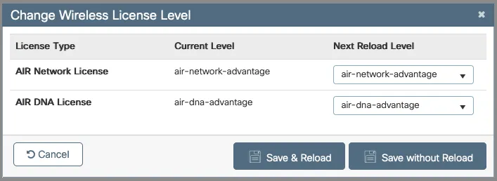
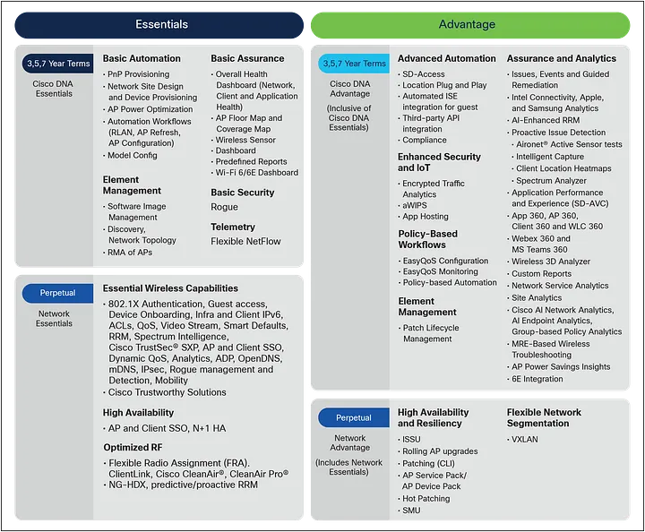
CẬP NHẬT: Hiện có yêu cầu cấp phép Network Advantage trên nền tảng CAT 9K.

Cấu hình

Configure Stack-wise Virtual ! tôi có 2 con Cat 9500. 

Trên switch 1:

switch#config t
switch(config)#
switch(config)#stackwise-virtual
Please reload the switch for Stackwise Virtual configuration to take effect
Upon reboot, the config will be part of running config but not part of start up config.
Switch(config-stackwise-virtual)# domain 10
Switch(config-stackwise-virtual)#exit
Switch(config)#interface Hu1/0/51
Switch(config-if)# description STACKWISE-VIRTUAL
Switch(config-if)# stackwise-virtual link 1
WARNING: SVL configuration will be ignored  on lower (1G) speed.
WARNING: All the extraneous configurations will be removed for HundredGigE1/0/51 on reboot
INFO: Upon reboot, the config will be part of running config but not part of start up config.
Switch(config-if)#interface Hu1/0/52
Switch(config-if)# description STACKWISE-VIRTUAL
Switch(config-if)# stackwise-virtual link 1
WARNING: SVL configuration will be ignored  on lower (1G) speed.
WARNING: All the extraneous configurations will be removed for HundredGigE1/0/52 on reboot
INFO: Upon reboot, the config will be part of running config but not part of start up config.
Switch(config-if)#
Switch(config-if)#interface TwentyFiveGigE1/0/47
Switch(config-if)# description STACKWISE-VIRTUAL
Switch(config-if)# stackwise-virtual dual-active-detection
WARNING: All the extraneous configurations will be removed for TwentyFiveGigE1/0/47 on reboot.
INFO: Upon reboot, the config will be part of running config but not part of start up config.
Switch(config-if)#interface TwentyFiveGigE1/0/48
Switch(config-if)# description STACKWISE-VIRTUAL
Switch(config-if)# stackwise-virtual dual-active-detection
WARNING: All the extraneous configurations will be removed for TwentyFiveGigE1/0/48 on reboot.
INFO: Upon reboot, the config will be part of running config but not part of start up config.
witch(config-if)#^Z
Switch#copy run start
Destination filename [startup-config]?
Building configuration...
[OK]
Switch#reload
Proceed with reload? [confirm]

Domain cho switch biết chúng đang ở trong domain nào. Khi hai switch cùng một domain, chúng biết rằng chúng được ghép nối với nhau. Trong cấu hình ví dụ này, domain là 10. Mọi domain có giá trị từ 1 đến 255 đều hợp lệ.

Mô tả cho các port kết nối là không bắt buộc, tôi làm điều đó chỉ vì lợi ích của người vận hành. Tôi là một kỹ sư triển khai nên sau khi hệ thống được triển khai, một nhóm kỹ sư khác sẽ vận hành nó. Tôi muốn gắn nhãn mô tả cho mọi thứ tôi làm để các kỹ sư theo dõi biết đó là gì. Nhưng bạn có thể thấy tôi định cấu hình các port tốc độ nhanh hơn cho Switch Virtual Link và các liên kết tốc độ thấp hơn cho Dual Active Detection links

Hãy chuyển sang Switch 2 !

Các lệnh trên switch 2 và switch 1 sẽ hoàn toàn giống nhau, ngoại trừ tập lệnh đầu tiên.

Switch#switch ren
Switch#switch renumber 2
WARNING: Changing the switch number may result in a configuration change for that switch.  The interface configuration associated with the old switch number will remain as a provisioned configuration. New Switch Number will be effective after next reboot. Do you want to continue?[y/n]? [yes]:
Switch#

Sau khi khởi động lại, đây sẽ là Switch 2. Trước khi reload, chúng ta cần định cấu hình các port Stackwise giống như chúng ta đã làm trên Switch 1. Đối với Switch 2, tôi sẽ bỏ qua các mô tả vì những port này sẽ không dính vào quá trình reload.

Switch#
Switch#config t
Enter configuration commands, one per line.  End with CNTL/Z.

Switch(config)#stackwise-virtual
Please reload the switch for Stackwise Virtual configuration to take effect
Upon reboot, the config will be part of running config but not part of start up config.
Switch(config-stackwise-virtual)#domain 10
Switch(config-stackwise-virtual)#interface Hu1/0/51

Switch(config-if)# stackwise-virtual link 1
WARNING: SVL configuration will be ignored  on lower (1G) speed.
WARNING: All the extraneous configurations will be removed for HundredGigE1/0/51 on reboot
INFO: Upon reboot, the config will be part of running config but not part of start up config.
Switch(config-if)#interface Hu1/0/52

Switch(config-if)# stackwise-virtual link 1
WARNING: SVL configuration will be ignored  on lower (1G) speed.
WARNING: All the extraneous configurations will be removed for HundredGigE1/0/52 on reboot
INFO: Upon reboot, the config will be part of running config but not part of start up config.
Switch(config-if)#interface TwentyFiveGigE1/0/47

Switch(config-if)# stackwise-virtual dual-active-detection
WARNING: All the extraneous configurations will be removed for TwentyFiveGigE1/0/47 on reboot.
INFO: Upon reboot, the config will be part of running config but not part of start up config.
Switch(config-if)#interface TwentyFiveGigE1/0/48

Switch(config-if)# stackwise-virtual dual-active-detection
WARNING: All the extraneous configurations will be removed for TwentyFiveGigE1/0/48 on reboot.
INFO: Upon reboot, the config will be part of running config but not part of start up config.
Switch(config-if)#exi
Switch(config)#exi
Switch#copy run start
Destination filename [startup-config]?
Building configuration...
[OK]
Switch#reload
Proceed with reload? [confirm]

Khi khởi động lại, một switch sẽ trì hoãn việc khởi động và đợi Switch 2 được phát hiện và tham gia vào stack. Sau khi cả hai switch được khởi động, bạn có thể sử dụng show switch để kiểm tra stack. Bạn có thể thấy HA Sync đang được tiến hành, như sau:

Bạn sẽ không thể sửa đổi cấu hình của switch cho đến khi HA Sync hoàn tất. Sẽ mất một vài phút. Để kiểm tra cấu hình Stackwise, hãy sử dụng show stackwise-virtual


witch#sho switch Switch/Stack Mac Address : b0c5.3ce8.0001 - Local Mac Address Mac persistency wait time: Indefinite H/W Current Switch# Role Mac Address Priority Version State ------------------------------------------------------------------------------------- *1 Active b0c5.3ce8.3480 1 V02 Ready 2 Standby b0c5.3ce8.4a60 1 V02 HA sync in progress Switch#

 show stackwise-virtual

Switch#sho stackwise-virtual
Stackwise Virtual Configuration:
--------------------------------
Stackwise Virtual : Enabled
Domain Number : 10

Switch  Stackwise Virtual Link  Ports
------  ----------------------  ------
1       1                       HundredGigE1/0/51
                                HundredGigE1/0/52
2       1                       HundredGigE2/0/51
                                HundredGigE2/0/52

Switch#

Bạn sẽ thấy số của port thay đổi. Các port của switch 1 sẽ là 1/0/1 và switch 2 sẽ là 2/0/1. Con số đầu tiên là switch vật lý, vì vậy nếu là 1, chúng tôi đang giải quyết các port của Switch 1, nếu là 2 thì chúng tôi đang giải quyết các port của Switch 2. Số tiếp theo đề cập module, giống như một card có thể lắp vào. Số cuối cùng là số port. Vì vậy, 2/0/35 là port 35 trên Switch 2.

Trên Chassis Platforms

Quy trình tương tự này có thể được sử dụng trên Chassis Platforms Catalyst 9606. Tuy nhiên, khi khởi động lại, bạn sẽ nhận thấy điều gì đó hơi khác một chút trên số port. Các số port sẽ giống như 1/5/0/24 – 1 là Khung, 5 là Card – trên 9606 bạn có thể có 4 card ở các khe 1, 2, 5 và 6, với các khe 3 và 4 được dành riêng cho Supervisor cards – số 0 đề cập đến các module và hiện tại không có mô-đun nào có sẵn cho nền tảng 9606, nhưng điều đó có thể thay đổi và số cuối cùng là số port. Vì vậy, trong ví dụ trước, bạn có Chassis 1, line card là khe cắm 5, module 0 và port là 24.

Cảnh báo

Một số lưu ý quan trọng cần biết:

Port Channels nằm trong khoảng từ 1 – 192 trên dòng switch Cat 9K – điều này không dành riêng cho Stackwise Virtual. Trên các dong switch Catalyst cũ hơn, bạn có thể có 301, 405 hoặc 550. Bạn cần cập nhật cấu hình của mình để đảm bảo các Port Channels của bạn nằm trong phạm vi hợp lệ đó.

Ngoài ra, số Port Channels 127 và 128 được dành riêng cho Stackwise. Vì vậy, nếu bạn hiện đang sử dụng những số đó, bạn sẽ cần sửa đổi cấu hình của mình để sử dụng các Port Channels thay thế.

VLAN 4094 được dành riêng cho Stackwise. Vì vậy, nếu bạn đang sử dụng VLAN đó hiện tại, bạn sẽ cần phải có kế hoạch di chuyển VLAN đó sang một VLAN khác.