IRF stack configuration (2 x HPE 5130 switches)

Introduction

In this article we will setup an IRF stack with two HP 5130 switches that run Comware OS.

What is IRF?

IRF (Intelligent Resilient Framework) is a proprietary virtualization/stacking technology used in some HPE switches. It has been developed originally by H3C, but later HPE acquired H3C.

IRF allows us to interconnect several switches and manage them as a single device. Besides that those interconnected switches form a single fabric and appear as a single node to other network devices.

IRF does not require any dedicated stacking modules, because it uses regular 10Gb Ethernet ports for stacking.

IRF Topology

Comware OS running switches support different number of switches in a stack depending on the switch model and the software version. The 5130 switches with the latest firmware support up to 9 switches in an IRF stack.

Switches can be interconnected in a ring or a daisy-chain manner. In this article we will configure two 5130-24G-4SFP+ (JG932A) switches as a single IRF stack. The topology of our stack is shown below:

The green links shown above are 10GbE connections.

Basic Concepts.

Below is a (very) short introduction to some of the concepts behind IRF technology. Please, read it, so you can understand why we make certain configuration changes on the switches.

IRF Member ID.

IRF Member ID is a unique ID that identifies a stack member. All switches in a stack should have different Member ID if we want them to form an IRF fabric. Default Member ID is 1. We will change Member ID of one of the switches.

IRF Member Priority.

Member priority is used to determine which switch will be selected as a master in our IRF stack. The switch with the higher priority will be elected the master. The default priority is 1.

IRF Port.

IRF Port is a logical interface on a switch used for communication with other stack members, and it should have at least one physical interface assigned to it. We can assign/bind several interfaces to an IRF port which will automatically become an aggregate link.

Configuration

Step 1. Configure IRF-SW1 (master)

Go to Switch 1 which we want to be a master and assign it a priority 32 (the default priority is 1) . The following commands will do this:

system-view
irf member 1 priority 32

You can then verify the settings on Switch 1 using display irf command:

You can see from the output that Member ID is 1 and Priority is 32

Step 2. Configure IRF Port on IRF-SW1

Now let’s create and configure our IRF port on Switch 1 which is required for IRF operation. We will create logical irf-port 1/1 and assign physical ports Ten-GigabitEthernet1/0/27 and Ten-GigabitEthernet1/0/28 to it. We should shutdown the physical interfaces before we can assign them to an IRF port. Below are the commands:

interface Ten-GigabitEthernet 1/0/27
shutdown

interface Ten-GigabitEthernet 1/0/28
shutdown

irf-port 1/1
port group interface Ten-GigabitEthernet1/0/27
port group interface Ten-GigabitEthernet1/0/28

Once you have added the physical ports to an IRF port you will see a message on the console, saying that you have to save your config and activate it using irf-port-configuration active command. Before doing this we will bring up our physical interfaces:

interface Ten-GigabitEthernet 1/0/27
undo shutdown

interface Ten-GigabitEthernet 1/0/28
undo shutdown

save
irf-port-configuration active

You can run display current-configuration and display irf configuration to verify the settings:


Step 3. Configure IRF-SW2 (slave)

Now let’s configure the Switch 2. The first thing we need to do is change its Member ID to 2, so it does not conflict with Switch 1. This will require a reboot. Run the following commands:

system-view
irf member 1 renumber 2
save
quit
reboot
You can run display irf command after reboot to make sure the new Member ID is in place:

Step 4. Configure IRF Port on IRF-SW2

Now we need to configure IRF port on Switch 2 and assign physical ports to it. We will create irf-port 2/2 and assign ports Ten-GigabitEthernet2/0/27 and Ten-GigabitEthernet2/0/28 to it. Note that all interface numbers now start with 2, because we have changed the Member ID of the switch.

Again, shutdown the interfaces before adding them to IRF port:

interface Ten-GigabitEthernet 2/0/27
shutdown

interface Ten-GigabitEthernet 2/0/28
shutdown

irf-port 2/2
port group interface Ten-GigabitEthernet2/0/27
port group interface Ten-GigabitEthernet2/0/28
The display current-configuration for the Switch 2 is shown below:

Now we can enable the interfaces and activate the IRF configuration:

interface Ten-GigabitEthernet 2/0/27
undo shutdown

interface Ten-GigabitEthernet 2/0/28
undo shutdown

save
irf-port-configuration active

Once you activate the IRF configuration, the Switch 2 will detect the Switch 1 and reboot. Note that Switch 2 will lose its current configuration, because it will become a member of a stack. Switch 1 will continue to operate, because it is a master.

Step 5. Verification

After Switch 2 boots up they will operate as a single logical unit. The display irf command confirms this:

As you can see, now we have a fully working IRF stack consisting of two HPE 5130 switches.

Conclusion

For further reading on IRF configuration you can have a look at this official guide from HP:

https://support.hpe.com/hpsc/doc/public/display?docId=c04771708

Thank you for reading 🙂

Stacking (VSF) Aruba Switches

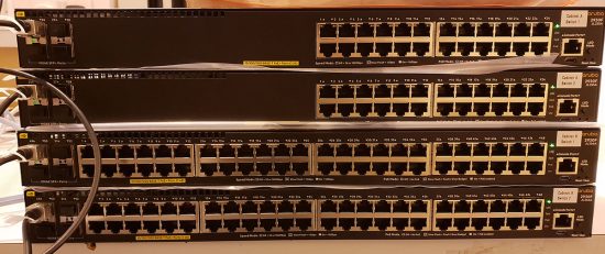
I noticed some shiny Aruba switches on the bench today, they were for a job my colleague is working on. (Note: Each switch in a stack should be the same, so these will need two stacks!)

Aruba Switch Stacking

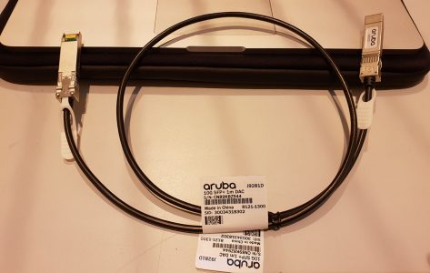
I work on the occasional HP/Aruba core switch, but it’s been a while since I did any work on distribution switches like these. The first thing I learned, was there’s no dedicated stacking cable for them. They simply use a 10Gb (Twinax / DAC) cable. Which I suppose is pretty straight forward, but it means you lose an SFP+ port (which is a bit pants).*

Aruba Stack Cable

*Note: You can stack with 1GB cables, but you can’t mix and match!

So I said “Give me a shoult when you stack them and I’ll take a nosey!”

Solution

In the ‘land of Aruba’ this is called creating a VSF (Virtual Switching Fabric). As you can see from the photo, these are 2930F Switches, and you can stack up to four switches in a VSF. The same stacking method is used on the 5400R (v3) and 5412, where you can link two 5400R or 5412’s).

Also this method is NOT to be confused with ‘Fabric Stacking’ which is available on the 2920,2930M,3800,3810M models, (that is more like Cisco FlexStack, with a dedicated 100Gb stack cable).

So, assuming you have your switch new and fresh, connect in with your console cable, and dedicate a port to use for VSF.

Aruba-2930F-24G-PoEP-4SFPP# conf t
Aruba-2930F-24G-PoEP-4SFPP(config)# vsf member 1 link 1 ethernet 25
All configuration on this port has been removed and port is placed in VSF mode.

Then place the switch into a VSF domain

Aruba-2930F-24G-PoEP-4SFPP(config)# vsf enable domain 1
This will save the current configuration and reboot the switch.

The switch will ask for a reboot, let it do so.

Repeat the procedure on the second switch, (but this will be member 2).

Aruba-2930F-24G-PoEP-4SFPP# conf t
Aruba-2930F-24G-PoEP-4SFPP(config)# vsf member 1 link 1 ethernet 25
All configuration on this port has been removed and port is placed in VSF mode.
Aruba-2930F-24G-PoEP-4SFPP(config)# vsf enable domain 1
This will save the current configuration and reboot the switch.

Once again let the switch reboot. 

Post reboot you will see the ports are ‘re-numbered’ 1/{port-number} on vsf member 1, 2/{port-number} on vsf member 2 etc.

Aruba-2930F-24G-PoEP-4SFPP# show interfaces
Status and Counters - Port Counters

                                                                 Flow Bcast
  Port         Total Bytes    Total Frames   Errors Rx Drops Tx  Ctrl Limit
  ------------ -------------- -------------- --------- --------- ---- -----
  1/1          0              0              0         0         off  0    
  1/2          0              0              0         0         off  0    
  1/3          0              0              0         0         off  0    
  1/4          0              0              0         0         off  0    
<---------------Output Removed For The Sake Of Brevity-------------->   
  1/10         0              0              0         0         off  0    
  1/11         0              0              0         0         off  0    
  1/12         0              0              0         0         off  0    
  1/13         0              0              0         0         off  0  
<---------------Output Removed For The Sake Of Brevity--------------> 
  1/19         0              0              0         0         off  0    
  1/20         0              0              0         0         off  0    
  1/21         0              0              0         0         off  0       
  1/25         1,496,823,949  23,354,845     0         0         off  0
<---------------Output Removed For The Sake Of Brevity--------------> 
  2/1          0              0              0         0         off  0    
  2/2          0              0              0         0         off  0    
  2/3          0              0              0         0         off  0    
  2/4          0              0              0         0         off  0    
<---------------Output Removed For The Sake Of Brevity--------------> 
  2/22         0              0              0         0         off  0    
  2/23         0              0              0         0         off  0    
  2/24         0              0              0         0         off  0    
  2/25         1,536,016,322  23,966,915     0         0         off  0    
  2/26         0              0              0         0         off  0    
  2/27         0              0              0         0         off  0    
  2/28         0              0              0         0         off  0    
 

If you need to Stack 3 or 4 Switches then you need to add a second link, and create a ring;

i.e.

  • Switch 2 (2nd link now to switch 3) vsf member 2 link 2 ethernet 26
  • Switch 3 (1st link to switch 2 ) vsf member 2 link 1 ethernet 25
  • Switch 3 (2nd link to switch 4 ) vsf member 2 link 2 ethernet 26
  • Switch 4 (1st link to switch 3 ) vsf member 4 link 1 ethernet 25
  • Switch 4 (2nd link to switch 1 ) vsf member 4 link 2 ethernet 26

Useful Aruba VSF Commands

show vsf or show vsf detail :  Shows the list of provisioned chassis members.

show vsf link or show vsf link detail : Shows the state of vsf links for all members.

show vsf lldp-mad status : Shows LLDP MAD (Multi-Active Detection).

show vsftrunk-designated-forwarder : Shows designated forwarders for each trunk.

ARUBA Controller firmware upgrade – (Best practise)

Either way will do but if you have Local controllers deployed, as a best practice upgrade the Standby first and then Master.

1. Upgrade the image of backup partition of Standby

2. Upgrade the Image of Backup partition of Master

3. Enable ” AP Image Preload” if you want to reduce the down time

4. Reload both the controllers.

Note : don’t forget to take the flash back up of the master before doing the above.

How to enable the ap image preload on aruba controller ?

This article explains how to trigger the AP image preload on the controller to minimize the downtime during the controller upgrade.

Feature Notes : The AP image preload allows the Access points (AP) to download the new image from the controller where it is terminated before the controller actually starts running the new version, hence reduces the downtime for the controller upgrade.

We can allow all the APs terminated on the controller or custom list of AP groups or individual APs to preload the image.

If a new AP associates to the controller when the preload feature is active, based on the AP group or AP name if it appears in the preload list the AP will start preload its image.

Environment : This feature is only supported on the 3600, 7200 Series and M3 controllers and applies to controllers running OS version 6.3 or later.

Network Topology : Standalone Master, Master-local

Configuration Steps :

Steps to trigger the AP image preload:

1. The controller should be upgraded first and before reboot, we need to trigger the AP image preloading in the same partition where the controller is upgraded.

(Aruba7240) #show image version
———————————-
Partition                : 0:0 (/dev/usb/flash1) **Default boot**
Software Version  : ArubaOS 6.3.1.3 (Digitally Signed – Production Build)
Build number        : 42233
Label                     : 42233
Built on                 : Tue Feb 11 12:31:53 PST 2014
———————————-
Partition                : 0:1 (/dev/usb/flash2)
Software Version  : ArubaOS 6.3.1.2 (Digitally Signed – Production Build)
Build number         : 41362
Label                     : 41362
Built on                  : Wed Dec 18 17:12:20 PST 2013
(Aruba7240) #show ap image-preload-status

AP Image Preload Parameters
—————————
Item    Value
—-    —–
Status  Inactive

——————

-To enable the AP image preload using the CLI, use the following command on the enable mode:

(Aruba7240) #ap image-preload activate ?
all-aps                 Activate image preload for all registered APs.
specific-aps          Activate image preload for specific APs as specified
by ‘ap image-preload ap-group’ and/or ‘ap
image-preload ap-name’

(Aruba7240) #ap image-preload activate all-aps partition 0

2. Once the controller is rebooted, the APs will reboot along with the controller and come up with less downtime as the image is already preloaded.
The ap image-preload will go to inactive state automatically after the controller reboots.

3.   For the controller’s next upgrade, again we need to upgrade the controller first and then need to trigger the AP image preload.

Note: The ap image preload must be inactive and should be triggered only after the controller image upgrade.


Verification : The same can be verified using the following commands:

(Aruba7240) #show ap image-preload-status

AP Image Preload Parameters
—————————
Item                            Value
—-                                —–
Status                          Active
Mode                           All APs
Partition                      1
Build                             41362
Max Simultaneous     Downloads  10
Start Time                   2014-03-18 12:05:04

AP Image Preload AP Status Summary
———————————-
AP Image Preload State  Count
———————-  —–
Preloaded               1
TOTAL                      1

AP Image Preload AP Status
————————–
AP Name   AP Group  AP IP         AP Type  Preload State  Start Time           End Time             Failure Count  Failure Reason
——-   ——–  —–         ——-  ————-  ———-           ——–             ————-  ————–
MasterAP  Master    10.10.10.252  105      Preloaded      2014-03-18 12:05:04  2014-03-18 12:06:15  0

(Aruba7240) #show ap image-preload-status-summary

AP Image Preload Parameters
—————————
Item                             Value
—-                                 —–
Status                           Active
Mode                            All APs
Partition                       1
Build                              41362
Max Simultaneous      Downloads  10
Start Time                    2014-03-18 12:05:04

AP Image Preload AP Status Summary
———————————-
AP Image Preload State  Count
———————-  —–
Preloaded               1
TOTAL                      1

(Aruba7240) #show ap image version
AP Image Versions On Controller
——————————-
6.3.1.2([email protected])#41362 Wed Dec 18 16:16:17 PST 2013
Access Points Image Version
—————————
AP            Running Image Version String                                                   Flash (Production) Image Version String                         Flash (Provisioning/Backup) Image Version String                    Matches  Num Matches  Num Mismatches  Bad Checksums  Bad Provisioning Checksums  Image Load Status
—            —————————-                                                   —————————————                         ————————————————                    ——-  ———–  ————–  ————-  ————————–  —————–
10.10.10.252  6.3.1.2([email protected])#41362 Wed Dec 18 16:16:17 PST 2013 6.3.1.3(p4build@port-royal)#42233 Tue Feb 11 11:29:58 PST 2014  6.1.3.4-3.1.0.0(p4build@cyprus)#35320 Sat Sep 15 13:43:44 PDT 2012  Yes      1            0               0              0                           Done
Total APs:1

Aruba – AP Troubleshooting

In order to make the WLAN function, the access points need connectivity to the controller.  Let’s review what an AP does during the boot process

Acquire IP address (can be static or acquired from DHCP)

  • IP address is required for communication with the controller using PAPI and GRE
  • To verify the access point properly acquires an IP you will need console access to the AP

Discover Controller

  • The AP goes through the following process in trying to discover a controller
  1. Statically assigned
  2.  DHCP Vendor Option 43
  3. ADP Multicast: Group Address 239.0.82.11 (requires multicast routing to be enabled on infrastructure)
  4. ADP L2 Broadcast
  5. DNS (aruba-master.<localsuffix>
  • The AP will follow the sequence exactly as above.  Once the AP learns a controller address, it terminates the discovery process and attempts to communicate with the learned address.  If the AP doesn’t receive a response from the learned address, then the AP will initiate a full reboot and start the process again

Update Code if necessary

  • AP Compares the code level to the controller’s code level
  • If the code revision matches the AP will continue the boot process
  • If the code revision does not match the AP will obtain the new code from the controller using FTP (TFTP is used on the initial join or if the AP is purged
  • The AP will automatically reboot after the code upgrade/downgrade
  • “show ap database” shows the current status of each AP (will list if upgrading, rebooting, etc)

Obtain Configuration Information

  • Once an AP connects to a controller and has compatible code, it will receive its configuration over PAPI
  • “show ap config ap-name <ap-name>” will show the AP configuration being pushed to the AP

Build GRE Tunnel

  • GRE is used to carry all of the wireless traffic between the AP and the local controller
  • A GRE tunnel is created per SSID per AP
  • The AP System Profile Controller LMS-IP setting tells the AP which controller the AP should terminate with
  • Be sure to allow Protocol 47 between the controllers and APs
  • “show ap debug system-status ap-name <ap-name>” – shows the communication status between the controller and AP
  • “show datapath tunnel table”shows the GRE tunnels established with the controller (look for prt 47)
  • “show ap debug counters”shows how many times an AP has rebooted or bootstrapped

Enable Radio

  • Once the GRE tunnel has been established the Radios will become enabled
  • “show profile-errors” – shows the list of invalid user created profiles.  An invalid user profile could cause the AP not to broadcast its assigned SSIDs.

Add a Local Controller to an Existing Master

Once a network has scaled up beyond a single controller capacity, a master/local architecture is recommended.  This allows the master controller to handle configuration and correlation while the locals can be responsible for handling the user traffic.

Steps to Add a local controller to an existing Master:

From the Master GUI:

Configuration -> Network -> Controller -> System Settings

–          Click New Local Controller IPSec Keys

–          Enter the IP Address of the local controller that you are adding

–          Enter an IPSec key

–          Re-Enter the IPSec key

–          Click Add

–          Click Apply (don’t forget)

–          Save Configuration

Or From the Master CLI:

localip <local ip address> ipsec <ipsec key>

From the Local GUI:

Configuration -> Network -> Controller -> System Settings

–          Select Controller Role Drop-Down and select Local

–          Enter the Master Controller IP (VRRP address if using master redundancy)

–          Enter IPSec Key  (Same key you entered on Master)

–          Click Apply

–          Reboot Controller

Or From the Local CLI:

masterip <master ip address> ipsec <ipsec key>

Master Controller Redundancy – Configuration

I’m going to walk through the steps for configuring master redundancy.  Here is my scenario:

Primary Master – 10.10.10.11 (should always be the master if up)

Backup Master – 10.10.10.12

VRRP IP – 10.10.10.15

VRRP ID – 10

VLAN – 10

First let’s start with the VRRP configuration on the Primary Master.

config t

vrrp 10

vlan 10

ip address 10.10.10.15

priority 110

preempt

description Preferred-Master

tracking master-up-time 30 add 20

no shut

Now let’s configure the Backup-Master

config t

vrrp 10

vlan 10

ip address 10.10.10.15

priority 100

preempt

description Backup-Master

tracking master-up-time 30 add 20

no shut

Once VRRP is up I need to associate the VRRP instance with master controller redundancy:

On the Primary:

config t

master-redundancy

master-vrrp 10

peer-ip-address 10.10.10.12 ipsec aruba123

On the Backup:

config t

master-redundancy

master-vrrp 10

peer-ip-address 10.10.10.11 ipsec aruba123

Once the VRRP instance is associated with master redundancy then I need to synchronize the WMS and local user database between the two controllers:

config t

database synchronize period <minutes> – defines the scheduled time to sync the databases (minimum should be 20 minutes)

Controller Redundancy

For my first technical deep dive let’s get into controller redundancy. During this post I will define the different types of redundancy in the Aruba system.  Please no controller vs controller-less rants!

Let’s begin by defining redundancy.  According to Wikipedia, redundancy is the duplication of critical components or functions of a system with the intention of increasing reliability of the system.  Unfortunately redundancy is left off a lot of wireless network designs due to cost.  In today’s mobility first environments redundancy needs to be implemented properly to ensure the reliability of the mission critical WLAN.

In Aruba world we have four levels of controller redundancy:

1)      Fully redundant – includes both master and local redundancy

2)      Redundancy aggregation – local redundancy

3)      Hot Standby – Local access points fail-over to Master

4)      No Redundancy – self-explanatory (far too common)

Master Redundancy:

The first controller redundancy model we will look at is Master redundancy.  The master controller is the control plane of the centralized WLAN.  The master controller is responsible for handling the global configuration of the WLAN system, location tracking, IDS event correlation and alerting.  The first question we should ask ourselves is what happens if the master controller is unavailable?  If the master becomes unavailable all master functions are lost (configuration, location tracking, and IDS) but the WLAN itself will continue to function.  New and existing clients will still be able to access the WLAN while the master controller is down.

To provide redundancy for the master controller we will setup a master/standby relationship with two controllers.  The Standby Master is a hot standby controller.  The Standby Master will not terminate AP sessions while it is the backup unit.  Updates on the state of the network are sent from the active Master to the Backup.  The two controllers sync the databases (WMS and local user) at a configured interval (typically 30 minutes).

VRRP (Virtual Router Redundancy Protocol) is used as the redundancy mechanism between the two controllers.  VRRP requires Layer2 adjacency.  The two master controllers will use a shared VRRP interface address.  The VRRP address is used by local controllers, access points, and mobility access switches to discover the master controller on the network.  The VRRP address can also be used by network administrators to access the management interface for the current master controller.

Local Redundancy:

Next we will look at Local Controller Redundancy.  The Local Controllers in an Aruba WLAN are responsible for AP termination, user authentication, and policy enforcement.  If a local controller fails and there is no backup the WLAN will become unavailable.

Local controllers have three methods for redundancy

Active-Active

  • two locals share a set of APs,  divide the load, acts as a backup for each other
  • if the two controllers are L2 adjacent, run two instances of VRRP with each controller acting as a primary for one instance and backup for the other instance
  • if the two controllers are not L2 adjacent then you will need to setup a LMS/Backup LMS IP address in the AP System Profile
  • You can also combine VRRP and LMS/Backup LMS for a more robust redundancy design, the VRRP addresses can be used as the LMS/Backup LMS IP addresses

Active-Standby

  • similar to Active-Active except one controller sits idle while the primary controller supports the full loads of APs and users
  • this model has a larger failure domain (increases latency because the full load must failover to the backup
  • typically this model utilizes the LMS/Backup LMS configuration
  • you could also use a single VRRP instance if the controllers are L2 adjacent

Many to One

  • typically used in remote networks where branch offices have local mobility controllers but redundancy onsite is not feasible
  • a large controller is deployed as the +1 controller at the data center
  • failure typically occurs across a WAN link
  • preemption should be enabled in this scenario due to the possible delay introduced by failing over to a remote site

No Redundancy

  • if the local goes down, no users can connect
  • Any AMs associated go down

Now that we know the different types of redundancy options we need to be aware of a few rules to ensure our network stays up according to plan.  There are four major rules in dealing with controller redundancy:

  1. Make sure the redundant controller can support the additional AP load during a failover event
  2. Make sure the same VLANs exist on both controllers and that named VLANs are mapped on the redundant controller
  3. Make sure the controllers are running the same OS version
  4. Make sure the redundant controller has the same license features enable and ensure you have enough license capacity to support the additional AP load during a failover event (AOS 6.3 will address this previous limitation)

In my next post I will begin configuring each of the different redundancy methods.