Juniper SRX VPN Troubleshooting

>show security ike security-associations 1.1.1.1 detail
>show security ike security-associations inactive
>show security ike active-peer
>show security ipsec security-associations vpn-name my_vpn
>show security ipsec security-associations vpn-name my_vpn traffic-selector t1
>show security ipsec inactive-tunnels
>show security ipsec statistics
>show interfaces st0.0 extensive

>show security flow session interface st0.0

>request security ike debug-enable local 173.167.224.13 remote 99.182.0.14 level 15

level 15 is a hidden command

>show security ike debug-status
>show log kmd

The below can narrow the output

>sh>show log kmd | match "ike|initiator|responder" 
>request security ike debug-disable

To troubleshoot inactive VPN 

>sh>show log kmd# set system syslog file kmd-logs daemon info
# set system syslog file kmd-logs match KMD
# commit

> show log kmd-logs | match peer_IP

To show number of packets through the tunnel use the command below. Narrow done by using “index”. As in the example below, a lot of packets are encrypted, but nothing back from neighbor:

srxA-2> show security ipsec security-associations          
  Total active tunnels: 1
  ID    Algorithm       SPI      Life:sec/kb  Mon lsys Port  Gateway   
  <131073 ESP:3des/sha1 e9618669 664/  unlim   -   root 500   192.168.11.1    
  >131073 ESP:3des/sha1 eda114c0 664/  unlim   -   root 500   192.168.11.1    

srxA-2> show security ipsec statistics index 131073  
ESP Statistics:
  Encrypted bytes:            15368
  Decrypted bytes:                0
  Encrypted packets:            113
  Decrypted packets:              0
AH Statistics:
  Input bytes:                    0
  Output bytes:                   0
  Input packets:                  0
  Output packets:                 0
Errors:
  AH authentication failures: 0, Replay errors: 0
  ESP authentication failures: 0, ESP decryption failures: 0
  Bad headers: 0, Bad trailers: 0

Reading the Logs:

Phase 1:
The following is an example from Kmd Log.   The most recent message is listed at the bottom. The above steps may display IKE Phase 2 and/or Phase 1 messages as below.   

Successful VPN connection:

Phase-1 [responder] done for local=ipv4(udp:500,[0..3]=1.1.1.2) remote=ipv4(udp:500,[0..3]=2.2.2.2)

Phase-2 [responder] done for p1_local=ipv4(udp:500,[0..3]=1.1.1.2) p1_remote=ipv4(udp:500,[0..3]=2.2.2.2) p2_local=ipv4_subnet(any:0,[0..7]=10.10.10.0/24) p2_remote=ipv4_subnet(any:0,[0..7]=192.168.168.0/24)

Failing due to phase 1 proposal mismatch:

Phase-1 [responder] failed with error(No proposal chosen) for local=unknown(any:0,[0..0]=) remote=ipv4(any:0,[0..3]=2.2.2.2)1.1.1.2:500 (Responder) <-> 2.2.2.2:500 { 011359c9 ddef501d – 2216ed2a bfc50f5f [-1] / 0x00000000 } IP; Error = No proposal chosen (14)

Resolution: Confirm that all phase 1 proposal elements match exactly on both peers. Confirm external interface is correct.

Failing due to unrecognized peer:

Unable to find phase-1 policy as remote peer:2.2.2.2 is not recognized.KMD_PM_P1_POLICY_LOOKUP_FAILURE: Policy lookup for Phase-1 [responder] failed for p1_local=ipv4(any:0,[0..3]=1.1.1.2) p1_remote=ipv4(any:0,[0..3]=2.2.2.2)1.1.1.2:500 (Responder) <-> 2.2.2.2:500 { 18983055 dbe1d0af – a4d6d829 f9ed3bba [-1] / 0x00000000 } IP; Error = No proposal chosen (14)

Resolution: Confirm peer ID type is correct (IP address, hostname, or user@hostname). Once peer ID type is confirmed then also confirm the ID itself is correct.

Failing due to pre-shared key mismatch:

1.1.1.2:500 (Responder) <-> 2.2.2.2:500 { e9211eb9 b59d543c – 766a826d bd1d5ca1 [-1] / 0x00000000 } IP; Invalid next payload type = 17 Phase-1 [responder] failed with error(Invalid payload type) for local=unknown(any:0,[0..0]=) remote=ipv4(any:0,[0..3]=2.2.2.2)

Resolution: Re-enter pre-shared key on both peers to ensure that they match.

Failing due to phase 2 proposal mismatch:

Phase-1 [responder] done for local=ipv4(udp:500,[0..3]=1.1.1.2) remote=ipv4(udp:500,[0..3]=2.2.2.2)1.1.1.2:500 (Responder) <-> 2.2.2.2:500 { cd9dff36 4888d398 – 6b0d3933 f0bc8e26 [0] / 0x1747248b } QM; Error = No proposal chosen (14)

Resolution: Confirm all phase 2 elements match exactly on both peers. Confirm tunnel policy exists.

Failing due to phase 2 proxy ID mismatch:

Phase-1 [responder] done for local=ipv4(udp:500,[0..3]=1.1.1.2) remote=ipv4(udp:500,[0..3]=2.2.2.2) Failed to match the peer proxy ids p2_remote=ipv4_subnet(any:0,[0..7]=192.168.168.0/24) p2_local=ipv4_subnet(any:0,[0..7]=10.10.20.0/24) for the remote peer:ipv4(udp:500,[0..3]=2.2.2.2)KMD_PM_P2_POLICY_LOOKUP_FAILURE: Policy lookup for Phase-2 [responder] failed for p1_local=ipv4(udp:500,[0..3]=1.1.1.2) p1_remote=ipv4(udp:500,[0..3]=2.2.2.2) p2_local=ipv4_subnet(any:0,[0..7]=10.10.20.0/24) p2_remote=ipv4_subnet(any:0,[0..7]=192.168.168.0/24)1.1.1.2:500 (Responder) <-> 2.2.2.2:500 { 41f638eb cc22bbfe – 43fd0e85 b4f619d5 [0] / 0xc77fafcf } QM; Error = No proposal chosen (14).

Resolution: Confirm that tunnel policy has correct address book entries as well as application or service. Check to see if manual proxy-id configured on gateway.

If there are no messages; make sure the correct IP address was used.   It is also possible that the Kmd Log filled up with other messages, so try to ping across the tunnel in order to attempt to bring the VPN up again.  If there are still no messages, refer to KB10100- How to Troubleshoot a Site-to-Site VPN Tunnel that wont come up.

Phase 2:
Phase-2 [responder] done for p1_local=ipv4(udp:500,[0..3]=1.1.1.2) p1_remote=ipv4(udp:500,[0..3]=2.2.2.2) p2_local=ipv4_subnet(any:0,[0..7]=10.10.10.0/24) p2_remote=ipv4_subnet(any:0,[0..7]=192.168.168.0/24)

Where 2.2.2.2 is the IP address of the remote firewall in question.  

The most common Phase 2 errors are:

Message: 1.1.1.2:500 (Responder) <-> 2.2.2.2:500 { cd9dff36 4888d398 – 6b0d3933 f0bc8e26 [0] / 0x1747248b } QM; Error = No proposal chosen (14)

Meaning:  The JUNOS device did not accept any of the IKE Phase 2 proposals that the specified IKE peer sent.

Action: Check the local VPN configuration. Either change the local configuration to accept at least one of the remote peer’s Phase 2 proposals, or contact the remote peer’s admin and arrange for the IKE configurations at both ends of the tunnel to use at least one mutually acceptable Phase 2 proposal. 

For assistance, see KB10123 – Received Message: Error = No proposal chosen (14).            

Message: Failed to match the peer proxy ids p2_remote=ipv4_subnet(any:0,[0..7]=192.168.168.0/24) p2_local=ipv4_subnet(any:0,[0..7]=10.10.20.0/24) for the remote peer:ipv4(udp:500,[0..3]=2.2.2.2)

Meaning:  No policy found matching the specified attributes

Action: The proxy-id must be an exact “reverse” match.  For example, the address book entries must have the same number of netmask bits, the list of services must match as well as the port numbers.  If any of these fields don’t match, the Phase 2 will fail.  Check the address and/or service book entries. 

Troubleshooting SRX chassis cluster

SRX chassis cluster bundles two devices together to provide high-availability. The cluster nodes must be the same model, have the cards placed in the same slots and must run the same software version. In addition at least two interconnect links must be present (one control and one fabric link). In newer releases the SRX supports dual fabric (high-end and branch SRXs) and dual control links (high-end SRXs only). The ports used for fabric link are defined through configuration. The definition of the ports for the control link on the other hand is not so flexible. The high-end SRXs (1000 and 3000 series) have dedicated ports for that and the 5000 series uses the ports on the SPC cards. On the branch SRX devices revenue ports (fixed ones) are converted to control ports.

Hardware preparation (card placement and cabling) is the initial task for creating the cluster. (The following link contains helpful information about cluster interconnections: http://www.juniper.net/techpubs/en_US/junos12.2/topics/task/operational/chassis-cluster-srx-series-hardware-connecting.html) The next step is to enable clustering on the  devices. On branch device the configuration must NOT contain any configuration of the interfaces that will be converted to control links for cluster to form correctly. The following commands provide an easy way to get rid of any potential dangerous configuration


  • delete interfaces
  • delete security
  • delete system host-name (leaving the host-name collides with the group configuration)

Continue reading “Troubleshooting SRX chassis cluster”

Stacking (VSF) Aruba Switches

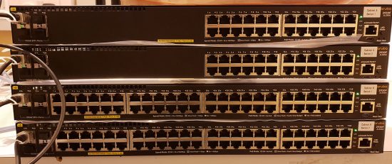
I noticed some shiny Aruba switches on the bench today, they were for a job my colleague is working on. (Note: Each switch in a stack should be the same, so these will need two stacks!)

Aruba Switch Stacking

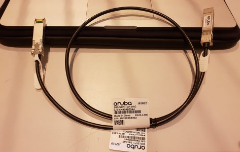
I work on the occasional HP/Aruba core switch, but it’s been a while since I did any work on distribution switches like these. The first thing I learned, was there’s no dedicated stacking cable for them. They simply use a 10Gb (Twinax / DAC) cable. Which I suppose is pretty straight forward, but it means you lose an SFP+ port (which is a bit pants).*

Aruba Stack Cable

*Note: You can stack with 1GB cables, but you can’t mix and match!

So I said “Give me a shoult when you stack them and I’ll take a nosey!”

Solution

In the ‘land of Aruba’ this is called creating a VSF (Virtual Switching Fabric). As you can see from the photo, these are 2930F Switches, and you can stack up to four switches in a VSF. The same stacking method is used on the 5400R (v3) and 5412, where you can link two 5400R or 5412’s).

Also this method is NOT to be confused with ‘Fabric Stacking’ which is available on the 2920,2930M,3800,3810M models, (that is more like Cisco FlexStack, with a dedicated 100Gb stack cable).

So, assuming you have your switch new and fresh, connect in with your console cable, and dedicate a port to use for VSF.

Aruba-2930F-24G-PoEP-4SFPP# conf t
Aruba-2930F-24G-PoEP-4SFPP(config)# vsf member 1 link 1 ethernet 25
All configuration on this port has been removed and port is placed in VSF mode.

Then place the switch into a VSF domain

Aruba-2930F-24G-PoEP-4SFPP(config)# vsf enable domain 1
This will save the current configuration and reboot the switch.

The switch will ask for a reboot, let it do so.

Repeat the procedure on the second switch, (but this will be member 2).

Aruba-2930F-24G-PoEP-4SFPP# conf t
Aruba-2930F-24G-PoEP-4SFPP(config)# vsf member 1 link 1 ethernet 25
All configuration on this port has been removed and port is placed in VSF mode.
Aruba-2930F-24G-PoEP-4SFPP(config)# vsf enable domain 1
This will save the current configuration and reboot the switch.

Once again let the switch reboot. 

Post reboot you will see the ports are ‘re-numbered’ 1/{port-number} on vsf member 1, 2/{port-number} on vsf member 2 etc.

Aruba-2930F-24G-PoEP-4SFPP# show interfaces
Status and Counters - Port Counters

                                                                 Flow Bcast
  Port         Total Bytes    Total Frames   Errors Rx Drops Tx  Ctrl Limit
  ------------ -------------- -------------- --------- --------- ---- -----
  1/1          0              0              0         0         off  0    
  1/2          0              0              0         0         off  0    
  1/3          0              0              0         0         off  0    
  1/4          0              0              0         0         off  0    
<---------------Output Removed For The Sake Of Brevity-------------->   
  1/10         0              0              0         0         off  0    
  1/11         0              0              0         0         off  0    
  1/12         0              0              0         0         off  0    
  1/13         0              0              0         0         off  0  
<---------------Output Removed For The Sake Of Brevity--------------> 
  1/19         0              0              0         0         off  0    
  1/20         0              0              0         0         off  0    
  1/21         0              0              0         0         off  0       
  1/25         1,496,823,949  23,354,845     0         0         off  0
<---------------Output Removed For The Sake Of Brevity--------------> 
  2/1          0              0              0         0         off  0    
  2/2          0              0              0         0         off  0    
  2/3          0              0              0         0         off  0    
  2/4          0              0              0         0         off  0    
<---------------Output Removed For The Sake Of Brevity--------------> 
  2/22         0              0              0         0         off  0    
  2/23         0              0              0         0         off  0    
  2/24         0              0              0         0         off  0    
  2/25         1,536,016,322  23,966,915     0         0         off  0    
  2/26         0              0              0         0         off  0    
  2/27         0              0              0         0         off  0    
  2/28         0              0              0         0         off  0    
 

If you need to Stack 3 or 4 Switches then you need to add a second link, and create a ring;

i.e.

  • Switch 2 (2nd link now to switch 3) vsf member 2 link 2 ethernet 26
  • Switch 3 (1st link to switch 2 ) vsf member 2 link 1 ethernet 25
  • Switch 3 (2nd link to switch 4 ) vsf member 2 link 2 ethernet 26
  • Switch 4 (1st link to switch 3 ) vsf member 4 link 1 ethernet 25
  • Switch 4 (2nd link to switch 1 ) vsf member 4 link 2 ethernet 26

Useful Aruba VSF Commands

show vsf or show vsf detail :  Shows the list of provisioned chassis members.

show vsf link or show vsf link detail : Shows the state of vsf links for all members.

show vsf lldp-mad status : Shows LLDP MAD (Multi-Active Detection).

show vsftrunk-designated-forwarder : Shows designated forwarders for each trunk.

Juniper Troubleshooting Commands

Managing configuration

>configure exclusive – Ngăn người khác sửa đổi trong khi ở chế độ cấu hình

#status –  Hiển thị người dùng hiện đang đăng nhập

#compare (filename | rollback n)

#commit | display detail – debug commit

#commit check

#commit comment

#commit confirmed

#commit at  [tt:mm | yyyy-mm-dd hh:mm | reboot], to cancel:

>clear system [commit | reboot ]

>show system commit

>show configuration

#load {set}  {merge | replace | override } {relative} [terminal | file] – paste – Ctrl+D to end

# show |   # compare (filename | rollback n)

# show |  display set

# show |  display changed

# show |  display detail

# show |  display omit statement

Configuration modification commands:

#annotate “xxxxx” – Chú thích cấu hình

#activate/deactivate

#copy / delete / rename – works with wildcards, e.g. delete fe*

#rename – string in configuration

#replace pattern

#protect / unprotect a statement

#exit configuration-mode

#quit

>show system rollback 10

>show system rollback compare 10 12

>show system commit

System

>show version {detail}

>request system reboot | power-off

>file [copy | list | delete | show | rename ]

>show system storage

>show chassis hardware detail

>show chassis alarms

>show chassis environment

>show chassis craft-interface – show router LED alarms

>show configuration | display detail

>show system users – ai đã đăng nhập vào hệ thống

>request system logout use username – forcefully logout a user

>request message all message “log out now”

>show system boot-messages – boot log

Interfaces/Hardware:

Hiển thị thông tin về bộ nhớ, nhiệt độ CPU, tải và thời gian hoạt động:

>show chassis routing engine 

Để xem phần cứng và SFP
Tổng quan về phần cứng
> show chassis hardware

fpc nào đang sử dụng
> show chassis fpc

Để hiển thị những chi tiết pic được lắp đặt trong một slot:
> show chassis pic pic-slot 0 fpc-slot 0

Xem công suất của fibre interface:
> show interfaces diagnostics optics

Logging

#set system syslog file messages any info à để lưu tất cả các logs vào tập tin

>show log messages | match LOGIN | match “Mar 16”

>file list detail /var/log = ls –al (to see permitions, etc.)

>clear log messages  – Để xoá nội dung tập tin Logs

>monitor start       messages  à Giám sát trực tiếp

>monitor list

>monitor stop à Stop giám sát

For more detailed information about a process, under the process level:

#set traceoptions file filenamefil world-readable

#set traceoptions flag all

>help syslog à Hiển thị thông tin logs hệ thống

Security Policies

View security policy:

> show security policies from-zone Proxy-DMZ to-zone Inside details

To check if traffic will pass through the security policies (useful when not able to generate traffic):

> show security match-policies from-zone Outside to-zone Inside protocol  xxx source-ip xxx source-port xxx destination-ip   xxx  destination-port xxxx


General Monitoring and troubleshooting

>monitor traffic interface ge-0/0/0

>monitor interface ge-0/0/0

>monitor traffic interface ge-0/2/3 matching “proto 89” write-file ospf.cap – matches proto 89 and writes it in ospf.cap

>show security flow session … options

>show system statistics – all packet types statistics for a device

>test policy             

Routing

>show route 
>show route terse – nice concise output with the following information: A-active, Destination, P-protocol, Prf-preference, Metric1,2 Next-hop, AS Patch)
>show route protocol [static|direct|ospf]
>show route forwarding-table
 to see active routes in the forwarding table

Troubleshoot OSPF

>show route forwarding-table à to see active routes in the forwarding table

>show route protocol ospf

>show ospf overview

>show ospf interaces

>show ospf neighbor

>show ospf dataset detail


>show ospf neighbor [extensive]

>clear ospf neighbor [192.168.254.225]

>show ospf statistics
>show ospf interface [extensive]
>show ospf route [abr|asbr|extern]
>show route protocol ospf 
 
>show ospf database [summary|brief]
>show ospf database [router|network|netsummary|asbrsummary|extern|nssa]
>show ospf database router advertising-router 10.0.3.3 detail
>show ospf database router area 0 extensive 
>show ospf database area 0 lsa-id extensive
>clear ospf database purge

>show ospf log


Troubleshoot NAT

+ Source

>show security nat source summary

>show security nat source rule

>show security nat source pool

+ Static

>show security nat static rule

+ Destination

>show security nat destination summary

>show security nat destination pool

>show security nat destination rule

>show security flow session

Firewall


>show firewall
>show firewall log
>clear firewall [all|filter-name|counter-name]
>show interfaces filters
>show interfaces policers
>show policer

******

Set Firewall Filter to count packets through the SRX:

# show interfaces ge-0/0/0

ge-0/0/0 {

   unit 0 {

      family inet {

         filter {

            input icmp-filter;

         }

         address 1.1.1.1/30; ## This address was already set on the interface

      }

   }

}

# show firewall family inet filter icmp-filter

icmp-filter {

   term 1 { ## This is the main term which will count the packets.

      from {

         source-address 3.3.3.3;

         destination-address 1.1.1.1;

         protocol icmp;

      }

      then {

         count icmp-counter; ## The icmp-counter will show the bytes/packets incrementing

         accept; ## This will accept the packets if you don’t want them to be dropped. You can use – “drop” or “reject” and/or “log” here.

      }

   }

Comware7: Configuration commit delay

In the old days it was quite common to schedule a device reboot e.g. 5 min ahead when ‘tricky’ remote device changes had to be performed over an in-band connection such as SSH/telnet. In case the config changes provided the desired result, the reboot would be cancelled. When the changes would have resulted in a lost management connection, the reboot would have reverted the device state to the previous config (assuming no ‘save’ was done).

Comware 7 now has a similar feature but without the device reboot, so this is an online ‘swap’ of the configuration without the reboot delay.

Note: This command is a one-off command, it is not saved in config and it needs to re-entered every time it is needed.

First set the time in the future when the auto-rollback is supposed to happen

[5900G-1]configuration commit delay ?
 INTEGER<1-65535>  Delay time in minutes
[5900G-1]configuration commit delay 2

%Jan  1 04:11:58:463 2011 5900G-1 SHELL/5/SHELL_COMMIT_DELAY: A configuration rollback will be performed in 2 minutes.

Now a config change is made, for example, the G1/0/1 description is set to ‘demo’

[5900G-1]int g1/0/1
[5900G-1-GigabitEthernet1/0/1]description demo1

Review the running config with the applied change

[5900G-1-GigabitEthernet1/0/1]dis cur int g1/0/1


 #
 interface GigabitEthernet1/0/1
 port link-mode bridge
 description demo1
 #
 return

When the administrator does not confirm the applied changes with the ‘commit’ command within the set delay time, the device will automatically rollback the configuration.

%Jan  1 04:08:28:315 2011 5900G-1 SHELL/5/SHELL_COMMIT_ROLLBACK: The configuration commit delay is overtime, a configuration rollback will be performed.
%Jan  1 04:08:36:403 2011 5900G-1 SHELL/5/SHELL_COMMIT_ROLLBACKDONE: The configuration rollback has been performed.

Now the running config has been reverted to the state before the commit delay was entered

[5900G-1-GigabitEthernet1/0/1]dis cur int g1/0/1
 #
 interface GigabitEthernet1/0/1
 port link-mode bridge
 #
 return

When the admin decides that the changes are fine, the configuration commit can be used. This will cancel the pending timer.

Again some configuration change is made

[5900G-1-GigabitEthernet1/0/1]description demo2
 [5900G-1-GigabitEthernet1/0/1]quit

Now the configuration commit is used

[5900G-1]configuration commit
%Jan  1 04:09:30:268 2011 5900G-1 SHELL/5/SHELL_COMMIT: The configuration has been committed.

And the running configuration now contains the applied changes

[5900G-1-GigabitEthernet1/0/1]dis cur int g1/0/1
#
 interface GigabitEthernet1/0/1
 port link-mode bridge
 description demo2
 #
 return

6509 went to ROMMON

A 6509 crashed and it went to ROMMON like this

System Bootstrap, Version 8.5(2)
Copyright (c) 1994-2007 by cisco Systems, Inc.
Cat6k-Sup720/SP processor with 524288 Kbytes of main memory

rommon 1 > boot
Initializing ATA monitor library...
string is bootdisk:s72033-ipservicesk9_wan-mz.122-33.SXH2a.bin
Loading image, please wait ...

Well, IOS and the boot image are there. Yet still no joy.

6509#sh bootv
BOOT variable = sup-bootdisk:,1;
CONFIG_FILE variable = 
BOOTLDR variable = 
Configuration register is 0x2102

Standby is not present.
6509#dir
Directory of sup-bootdisk:/

    1  -rw-    74573284   Aug 6 2008 23:02:28 +10:00  s72033-ipservicesk9_wan-mz.122-33.SXH2a.bin
    2  -rw-    33554432   Aug 7 2008 08:27:28 +10:00  sea_log.dat
    3  -rw-      137219   Oct 9 2008 15:04:02 +11:00  crashinfo_20081009-040403

512106496 bytes total (403832832 bytes free)
6509#conf t
Enter configuration commands, one per line.  End with CNTL/Z.
6509(config)#boot system flash sup-bootflash:s72033-ipservicesk9_wan-mz.122-33.SXH2a.bin
6509(config)#do wr
Building configuration...
[OK]
6509(config)#exit
6509#sh run | i boot
boot-start-marker
boot system flash sup-bootflash:s72033-ipservicesk9_wan-mz.122-33.SXH2a.bin
boot-end-marker
6509(config)#do wr
Building configuration...
[OK]
6509(config)#exit
6509#reload
Proceed with reload? [confirm]
Oct 15 16:28:20.057 AEDT: %SYS-SP-3-LOGGER_FLUSHING: System pausing to ensure console debugging output.
Oct 15 16:28:20.057 AEDT: %OIR-SP-6-CONSOLE: Changing console ownership to switch processor
Oct 15 16:28:23.337 AEDT: %SYS-SP-3-LOGGER_FLUSHING: System pausing to ensure console debugging output.

***
*** --- SHUTDOWN NOW ---
***

Oct 15 16:28:23.337 AEDT: %SYS-SP-5-RELOAD: Reload requested
Oct 15 16:28:23.337 AEDT: %OIR-SP-6-CONSOLE: Changing console ownership to switch processor

System Bootstrap, Version 8.5(2)
Copyright (c) 1994-2007 by cisco Systems, Inc.
Cat6k-Sup720/SP processor with 524288 Kbytes of main memory


rommon 1 > 

Apparently, this is what I needed to do.

rommon 1 > dir bootflash:
Initializing ATA monitor library...
Directory of bootflash:

2      74573284  -rw-     s72033-ipservicesk9_wan-mz.122-33.SXH2a.bin
936    33554432  -rw-     sea_log.dat
13202    137219    -rw-     crashinfo_20081009-040403

rommon 2 > set
PS1=rommon ! > 
LOG_PREFIX_VERSION=1
SLOTCACHE=cards;
SWITCH_NUMBER=0
BOOT=bootflash:,1;bootflash:s72033-ipservicesk9_wan-mz.122-33.SXH2a.bin,1;
RET_2_RTS=16:39:18 AEDT Wed Oct 15 2008
NT_K=0:0:0:0
CV=bootdisk:s72033-ipservicesk9_wan-mz.122-33.SXH2a.bin
BSI=0
RET_2_RCALTS=
PF_REDUN_CRASH_COUNT=0
RANDOM_NUM=655707222
?=0

rommon 3 > BOOT=s72033-ipservicesk9_wan-mz.122-33.SXH2a.bin

rommon 4 > sync

rommon 5 > set
PS1=rommon ! > 
LOG_PREFIX_VERSION=1
SLOTCACHE=cards;
SWITCH_NUMBER=0
RET_2_RTS=16:39:18 AEDT Wed Oct 15 2008
NT_K=0:0:0:0
CV=bootdisk:s72033-ipservicesk9_wan-mz.122-33.SXH2a.bin
BSI=0
RET_2_RCALTS=
PF_REDUN_CRASH_COUNT=0
RANDOM_NUM=655707222
BOOT=s72033-ipservicesk9_wan-mz.122-33.SXH2a.bin
?=0
rommon 6 > confreg 2102
rommon 7 > reset

Connecting to another node in a Juniper HA Cluster

When your logged in to one node of  Juniper cluster which has multiple nodes since its a HA Cluster. Below prompt show shell connection to node0.
To move to the another node let say node0 to node1, you just need this command below.

— JUNOS 11.4R10.3 built 2013-11-15 06:56:20 UTC
{primary:node0}
root@FIREWALL-PRI-SRX240> 

root@FIREWALL-PRI-SRX240> request routing-engine login node 1

— JUNOS 11.4R10.3 built 2013-11-15 06:56:20 UTC
{secondary:node1}
root@FIREWALL-PRI-SRX240>

As you can see, the shell now indicates that the prompt is now om node1 (which is the secondary).

RUCKUS ICX7150-C12P – BASIC LAYER 3 SERVICES

n the previous posts focused on the topic of configuring Ruckus ICX Switches, we got the ICX 7150-C12P up and running and upgraded to the latest Layer 3 image.  In this post I want to start configuring it to act as a Layer 3 switch for my Ruckus laboratory environment.

If you are learning about Ruckus ICX Switches and their capabilities, I recommend reviewing the following useful documentation (along with everything else) available on the Ruckus support site:

  • Command Reference Guide
  • Layer 2 Switching Configuration Guide
  • Layer 3 Routing Configuration Guide
  • DHCP Configuration Guide

Configuring IP Addresses

The first thing I am going to need is an IP address on the ICX switch.  The ICX layer 3 switch firmware gives you the ability to define an IP Address on the following types of interfaces:

  • Ethernet Ports
  • Virtual Interfaces / Virtual Ethernet  (VE)
  • Loopback interfaces
  • GRE Tunnels

Ethernet Interfaces

You can assign an IP address directly to a specified Ethernet interface.  For example you can assign the address 10.0.0.1/24 to Ethernet interface 1/1/1 on the switch.  You can also load multiple IP addresses onto a given Ethernet interface.  This is useful in scenarios where you know exactly which Ethernet Interface the traffic will arrive on.  A good example of when to apply this configuration is if you are running a point to point link between two locations using a specific interface on either side of the link.

Example

As it turns out, this is exactly the kind of scenario I have in my home laboratory between the Ruckus ICX7150-C12P and the Internet NAT router!  Here is an example where I assign an IP address directly to uplink port 1/2/2 on the ICX7150 switch in my laboratory.

SSH@RobLab_7150_C12P_1#configure terminal
SSH@RobLab_7150_C12P_1(config)#interface ethernet 1/2/2 
SSH@RobLab_7150_C12P_1(config-if-e1000-1/2/2)#ip address 172.31.254.2/30
SSH@RobLab_7150_C12P_1(config-if-e1000-1/2/2)#exit
SSH@RobLab_7150_C12P_1(config)#write memory
Flash Memory Write (8192 bytes per dot)
. 
Write startup-config done. Copy Done. 
SSH@RobLab_7150_C12P_1(config)#

Virtual Interfaces

A virtual interface is the same as a “sub interface” on Cisco routers and is referred to as Virtual Ethernet or VE in Ruckus ICX nomenclature.  A virtual interface acts as the layer 3 interface to terminate VLAN tagged Ethernet traffic.  The advantage of this interface type over an Ethernet interface is that you can aggregate traffic entering the switch via multiple Ethernet interfaces.

Consider a scenario in which you have Layer 2 traffic tagged with VLAN 100 entering the Layer 3 switch. You want the Layer 3 switch to route that traffic to destinations on other subnets, but the traffic may enter through multiple ethernet interfaces.  The Layer 3 switch solves this scenario with a Virtual Interface that can be assigned to multiple Ethernet interfaces.

Maximum Virtual Interfaces

Be aware that your chosen switch model may have some limitations in terms of the number of Virtual Interfaces it can support. Consult the data sheet and configuration guides of your switch model and firmware releases to be certain of how many Virtual Interfaces (VEs) are supported.

Configuring a Virtual Interface

Management VLAN

The management VLAN exists to allow me to access all physical and virtual network components from a single location.  The Management VLAN will be exclusively enabled, untagged on Ethernet interface 1/1/12.  The management VLAN will be assigned to

RobLab_7150_C12P_1>enable 
User Name:<user> 
Password: 
RobLab_7150_C12P_1#conf t 
RobLab_7150_C12P_1(config)#vlan 101 name MGMT 
RobLab_7150_C12P_1(config-vlan-100)#untagged ethernet 1/1/12 
Added untagged port(s) ethe 1/1/12 to port-vlan 101. 
RobLab_7150_C12P_1(config-vlan-100)#router-interface ve 2 
RobLab_7150_C12P_1(config-vlan-100)#interface ve 2 
RobLab_7150_C12P_1(config-vif-2)#ip address 172.31.255.1/24 
RobLab_7150_C12P_1(config-vif-2)#write memory 
Flash Memory Write (8192 bytes per dot)  
. 
Write startup-config done. 
Copy Done. 
RobLab_7150_C12P_1(config-vif-2)#exit 
RobLab_7150_C12P_1(config)#exit 
RobLab_7150_C12P_1#

x86 Hosts VLAN

The x86_Hosts VLAN (VLAN 100) will be exclusively enabled, untagged on ethernet interfaces 1/1/1 to 1/1/6.  The x86 Hosts VLAN will be assigned to router-interface ve 1 with IP address 172.31.0.1/24.  This will allow me to gain direct access to the switch CLI should anything go wrong with my Management VLAN.

RobLab_7150_C12P_1>enable
User Name:<user>
Password:
RobLab_7150_C12P_1#conf t
RobLab_7150_C12P_1(config)#vlan 100 name x86_Hosts
RobLab_7150_C12P_1(config-vlan-100)#untagged ethernet 1/1/1 to 1/1/6
Added untagged port(s) ethe 1/1/1 to 1/1/6 to port-vlan 100.
RobLab_7150_C12P_1(config-vlan-100)#router-interface ve 1
RobLab_7150_C12P_1(config-vlan-100)#interface ve 1
RobLab_7150_C12P_1(config-vif-1)#ip address 172.31.0.1/24
RobLab_7150_C12P_1(config-vif-1)#write memory
Flash Memory Write (8192 bytes per dot) 
.
Write startup-config done.
Copy Done.
RobLab_7150_C12P_1(config-vif-1)#exit
RobLab_7150_C12P_1(config)#exit
RobLab_7150_C12P_1#

Additional VLANs

Additional VLANs will be enabled on the switch to provide Layer 2 services on an as needed basis in my testing.  These will include VLANs for Access Points and Client Subnets.  These VLANs will simply allow the traffic to pass through to the routers in the virtual lab.

Loopback Interfaces & GRE Interfaces

I am rather conspicuously not talking about configuring these interfaces at this point in time.  But I believe the topic will come up in a later post.  If you cannot wait, I strongly recommend reading the Ruckus ICX Layer 3 Routing Configuration Guide.

Configuring DHCP

I will require a DHCP server in the Management VLAN that provides addresses to clients as they connect.  I also want this DHCP server to work on the out of band management port, just in case my access via WLAN fails or using a cable is faster!

Let me start by saying there is a ton you can do with this DHCP server and the DHCP capabilities in the switch.  The below configuration is truly trivial.

RobLab_7150_C12P_1#conf t
RobLab_7150_C12P_1(config)#ip dhcp-server enable
RobLab_7150_C12P_1(config)#ip dhcp-server pool mgmt_1      
RobLab_7150_C12P_1(config-dhcp-mgmt_1)#network 172.31.255.0/24
RobLab_7150_C12P_1(config-dhcp-mgmt_1)#dhcp-default-router 172.31.255.1
RobLab_7150_C12P_1(config-dhcp-mgmt_1)#dns-server 172.31.255.1
RobLab_7150_C12P_1(config-dhcp-mgmt_1)#excluded-address 172.31.255.1 172.31.255.99
RobLab_7150_C12P_1(config-dhcp-mgmt_1)#lease 0 6 0
RobLab_7150_C12P_1(config-dhcp-mgmt_1)#deploy      
RobLab_7150_C12P_1(config)#ip dhcp-server server-identifier 172.31.255.1
RobLab_7150_C12P_1(config)#write memory

Note: If you ever change the DHCP pool config, remember to issue the DEPLOY command again, otherwise the DHCP address pool will simply remain in a “pending” state after your changes!

Useful Commands

Here are some useful commands to check the status of the DHCP server and the address pools.

SSH@RobLab_7150_C12P_1#show ip dhcp-server        
  address-pools   Display all address pools
  binding         Display DHCP lease-binding database
  flash           Displays the lease-binding database stored in flash memory
  summary         Displays the DHCP servers statistics 
---
SSH@RobLab_7150_C12P_1#show ip dhcp-server summary       
DHCP Server Summary:
                    Total number of active leases:  2
           Total number of deployed address-pools:  1
         Total number of undeployed address-pools:  0
                                    Server uptime:  04d:09h:32m:16s
---
SSH@RobLab_7150_C12P_1#show ip dhcp-server address-pools 
Showing all address pool(s):
                    Pool Name:  mgmt_1
 Time elapsed since last save:  00d:00h:29m:34s
Total number of active leases:  2
           Address Pool State:  active
        IP Address Exclusions:  172.31.255.1 172.31.255.99
      Pool Configured Options:
          dhcp-default-router:  172.31.255.1
                   dns-server:  10.0.0.254  8.8.8.8 
                        lease:  0 6 0
                      network:  172.31.255.0 255.255.255.0
---
SSH@RobLab_7150_C12P_1#show ip dhcp-server binding       
Bindings from all pools:
        IP Address    Client-ID/        Lease expiration Type
                      Hardware address
    172.31.255.100    c0d0.1274.2590   000d:05h:58m:15s   Automatic
    172.31.255.101    48d7.05be.758d   000d:05h:59m:24s   Automatic
SSH@RobLab_7150_C12P_1#

Routing Between Subnets

To provide Internet access for the subnets I have configured above, I must provide a default route to the internet.  Internet access in the laboratory is provided by a Mikrotik router (172.31.254.1) connected to the Ethernet Interface 1/2/2 on the ICX7150 switch.

Ruckus ICX switches have a feature called Integrated Switch Routing (ISR), which allows routing traffic between virtual interfaces in the switch without the need for an external router.  You don’t (shouldn’t) need to do anything to enable this feature.  You do, however, have to configure routes to reach external entities using either static or dynamic routing protocols.  Thus far I am sticking to static routing protocols.

Setting a Default Route

RobLab_7150_C12P_1#conf t RobLab_7150_C12P_1(config)#
SSH@RobLab_7150_C12P_1(config)#ip route 0.0.0.0/0 172.31.254.1   
SSH@RobLab_7150_C12P_1(config)#write memory
Flash Memory Write (8192 bytes per dot) 
.
Write startup-config done.
Copy Done.
SSH@RobLab_7150_C12P_1(config)#exit
SSH@RobLab_7150_C12P_1#

About Management Access

On the Ruckus ICX layer 3 switch you can use any one of the configured IP addresses on the switch for management access to the switch.  I can access the switch over ssh via 172.31.0.1, 172.31.255.1 and 172.31.254.2.  I will discuss hardening the switch configuration in a later post.

Quick Summary Config

Here is the current running config of the switch (also the config startup!) to summarize what we have done so far.

SSH@RobLab_7150_C12P_1#show run
Current configuration:
!
ver 08.0.61T213
!
stack unit 1
  module 1 icx7150-c12-poe-port-management-module
  module 2 icx7150-2-copper-port-2g-module
  module 3 icx7150-2-sfp-plus-port-20g-module
!
...
vlan 1 name DEFAULT-VLAN by port
!
vlan 100 name x86_Hosts by port
 untagged ethe 1/1/1 to 1/1/6 
 router-interface ve 1
!
vlan 101 name MGMT by port
 tagged ethe 1/1/12 
 router-interface ve 2
!
...
aaa authentication enable default local
aaa authentication login default local
aaa authentication login privilege-mode
hostname RobLab_7150_C12P_1
ip dhcp-server enable
ip dhcp-server server-identifier 172.31.255.1
!
ip dhcp-server pool mgmt_1
 dhcp-default-router 172.31.255.1 
 dns-server 172.31.255.1 
 excluded-address 172.31.255.1 172.31.255.99
 lease 0 6 0                                                      
 network 172.31.255.0 255.255.255.0
 deploy
!
ip route 0.0.0.0/0 172.31.254.1
!
username <user> password .....
!
...
interface ethernet 1/2/2
 ip address 172.31.254.2 255.255.255.252
!
interface ve 1
 ip address 172.31.0.1 255.255.255.0
!
interface ve 2
 ip address 172.31.255.1 255.255.255.0
!
...
ip ssh  key-exchange-method dh-group14-sha1 
!
!
end
SSH@RobLab_7150_C12P_1#


zoning commands in Brocade fabric switch | Process for zoning request

Brocade

About

Brocade Communications Systems, Inc. is an American technology company specializing in data and storage networking products. Originally known for its leadership in Fibre Channel storage networks, the company has expanded its focus to include a wide range of products for New IP and Third platform technologies.

Brocade was founded in August 1995, by Seth Neiman (a venture capitalist, a former executive from Sun Microsystems and a professional auto racer), Kumar Malavalli (a co-author of the Fibre Channel specification).

The company’s first product, SilkWorm, which was a Fibre Channel Switch, was released in early 1997. A second generation of switches was announced in 1999.

On January 14, 2013, Brocade named Lloyd Carney as new chief executive Officer.

Brocade FC Switch have so many models with the port variations, the details are below

 
List of Brocade FC switches 


Work flow for zoning activity

The Platform team will inform you that they are going to provision a new server in the environment and requests you to give the free port details on the switches which are exists in the data center.

Once you share the information to Platform team, they co-ordinate with the Data center guys to lay the cables between the server and switch. (Already the storage ports or tape library are connected to the switch).

After laying the cables, Platform team will requests you to check the connectivity and they shares the server HBA WWPN to verify with the connected one.

 
Physical cabling between Server and storage through Switch with Single path


Physical cabling between Server and storage through Switch with Multipath

Zoning can be done in 7 simple steps, the pictorial diagram is as follows.

 
Steps to perform zoning

Zoning steps:-

  1. Identify the WWPN of Server HBA and Storage HBA.
  1. Create Alias of server and storage HBA’s.

     Alicreate

  1. Create zones for server and storage by using the command

     Zonecreate

  1. We need to check whether active configurations is present or not by using the command.

      Cfgactvshow

  1. If an active configuration already exits we just need to add the zone to this, by using the command.

     Cfgactvadd

  1. If not there we need to create new active configuration by using the command.

      Cfgcreate

  1. Save it and enable it.

Please find the example for zoning,

alicreate “ser ver_hba”,”11:11:11:11:11:11:11:11″

alicreate “storage_hba”,”22:22:22:22:22:22:22:22″

zonecreate “server_hba-storage_hba”,” ser ver_hba; storage_hba “

cfgcreate “cfg_switch1″,” server_hba-storage_hba “

cfgenable ” cfg_switch1″

cfgsave

Brocade switches uses both web and CLI, the table below displays some but not all the CLI commands.

help

prints available commands

switchdisabled

disable the switch

switchenable

enable the switch

licensehelp

license commands

diaghelp

diagnostic commands

configure

change switch parameters (BB credits, etc)

diagshow

POST results since last boot

routehelp

routing commands

switchshow

display switch show (normally first command to run to obtain switch configuration)

supportshow

full detailed switch info

portshow

display port info

nsshow

namesever contents

nsallshow

NS for full fabric

fabricshow

Fabric information

version

firmware code revision

reboot

full reboot with POST

fastboot

reboot without POST

B-Series (Brocade) zoning commands are detailed in the below table

zonecreate (zone)

create a zone

zoneshow

shows defined and effective zones and configurations

zoneadd

adds a member to a zone

zoneremove

removes a member from a zone

zonedelete

delete a zone

cfgcreate (zoneset)

create a zoneset configuration

cfgadd

adds a zone to a zone configuration

cfgshow

display the zoning information

cfgenable

enable a zone set

cfgsave

saves defined config to all switches in fabric across reboots

cfgremove

removes a zone from a zone configuration

cfgdelete

deletes a zone from a zone configuration

cfgclear

clears all zoning information (must disable the effective config first)

cfgdisable

disables the effective zone set

B-series creating a zone commands

Creating zone by WWN

zonecreate “zone1”, “20:00:00:e0:69:40:07:08 ; 50:06:04:82:b8:90:c1:8d”

Create a zone configuration

cfgcreate “test_cfg”, “zone1 ; zone2”

saving the zone configuration

cfgsave (this will save across reboots)

enable the zone configuration

cfgenable “test_cfg”

saving the zone configuration

cfgsave

view zoning information

zoneshow or cfgshow

aliAdd   Add a member to a zone alias

aliCopy   Copy a zone alias

aliCreate  Create a zone alias

aliDelete  Delete a zone alias

aliRemove  Remove a member from a zone alias

aliRename  Rename a zone alias

aliShow   Print zone alias information

cfgAdd   Add a member to a configuration

cfgCopy   Copy a zone configuration

cfgCreate  Create a zone configuration

cfgDelete  Delete a zone configuration

cfgRemove  Remove a member from a configuration

cfgRename  Rename a zone configuration

cfgShow   Print zone configuration information

zoneAdd   Add a member to a zone

zoneCopy  Copy a zone

zoneCreate  Create a zone

zoneDelete  Delete a zone

zoneRemove  Remove a member from a zone

zoneRename  Rename a zone

zoneShow  Print zone information

cfgClear  Clear all zone configurations

cfgDisable  Disable a zone configuration

cfgEnable  Enable a zone configuration

cfgSave   Save zone configurations in flash

cfgSize   Print size details of zone database

cfgActvShow  Print effective zone configuration

cfgTransAbort  Abort zone configuration transaction

ARUBA Controller firmware upgrade – (Best practise)

Either way will do but if you have Local controllers deployed, as a best practice upgrade the Standby first and then Master.

1. Upgrade the image of backup partition of Standby

2. Upgrade the Image of Backup partition of Master

3. Enable ” AP Image Preload” if you want to reduce the down time

4. Reload both the controllers.

Note : don’t forget to take the flash back up of the master before doing the above.