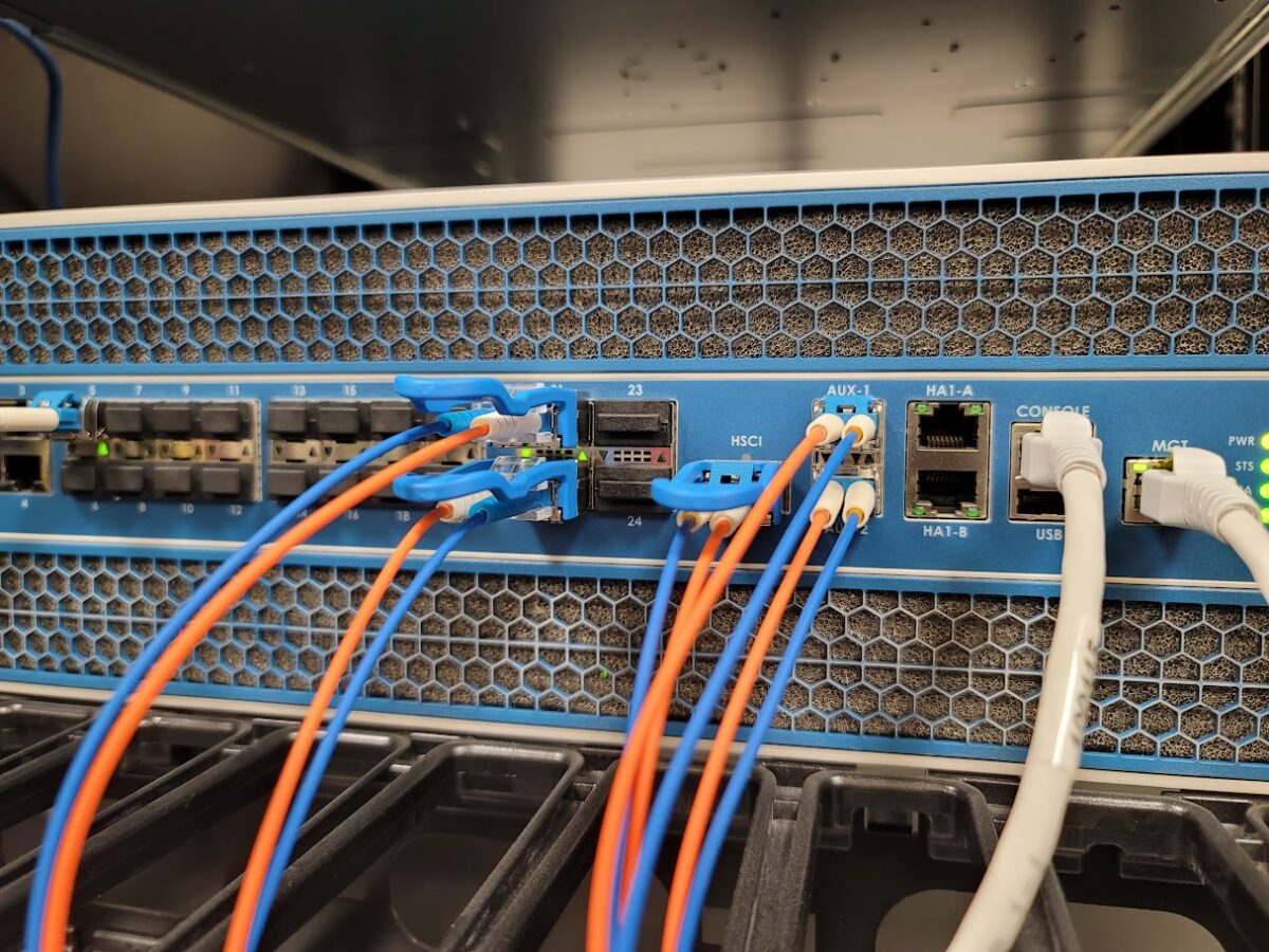
6509 went to ROMMON

A 6509 crashed and it went to ROMMON like this

System Bootstrap, Version 8.5(2)
Copyright (c) 1994-2007 by cisco Systems, Inc.
Cat6k-Sup720/SP processor with 524288 Kbytes of main memory

rommon 1 > boot
Initializing ATA monitor library...
string is bootdisk:s72033-ipservicesk9_wan-mz.122-33.SXH2a.bin
Loading image, please wait ...

Well, IOS and the boot image are there. Yet still no joy.

6509#sh bootv
BOOT variable = sup-bootdisk:,1;
CONFIG_FILE variable = 
BOOTLDR variable = 
Configuration register is 0x2102

Standby is not present.
6509#dir
Directory of sup-bootdisk:/

    1  -rw-    74573284   Aug 6 2008 23:02:28 +10:00  s72033-ipservicesk9_wan-mz.122-33.SXH2a.bin
    2  -rw-    33554432   Aug 7 2008 08:27:28 +10:00  sea_log.dat
    3  -rw-      137219   Oct 9 2008 15:04:02 +11:00  crashinfo_20081009-040403

512106496 bytes total (403832832 bytes free)
6509#conf t
Enter configuration commands, one per line.  End with CNTL/Z.
6509(config)#boot system flash sup-bootflash:s72033-ipservicesk9_wan-mz.122-33.SXH2a.bin
6509(config)#do wr
Building configuration...
[OK]
6509(config)#exit
6509#sh run | i boot
boot-start-marker
boot system flash sup-bootflash:s72033-ipservicesk9_wan-mz.122-33.SXH2a.bin
boot-end-marker
6509(config)#do wr
Building configuration...
[OK]
6509(config)#exit
6509#reload
Proceed with reload? [confirm]
Oct 15 16:28:20.057 AEDT: %SYS-SP-3-LOGGER_FLUSHING: System pausing to ensure console debugging output.
Oct 15 16:28:20.057 AEDT: %OIR-SP-6-CONSOLE: Changing console ownership to switch processor
Oct 15 16:28:23.337 AEDT: %SYS-SP-3-LOGGER_FLUSHING: System pausing to ensure console debugging output.

***
*** --- SHUTDOWN NOW ---
***

Oct 15 16:28:23.337 AEDT: %SYS-SP-5-RELOAD: Reload requested
Oct 15 16:28:23.337 AEDT: %OIR-SP-6-CONSOLE: Changing console ownership to switch processor

System Bootstrap, Version 8.5(2)
Copyright (c) 1994-2007 by cisco Systems, Inc.
Cat6k-Sup720/SP processor with 524288 Kbytes of main memory


rommon 1 > 

Apparently, this is what I needed to do.

rommon 1 > dir bootflash:
Initializing ATA monitor library...
Directory of bootflash:

2      74573284  -rw-     s72033-ipservicesk9_wan-mz.122-33.SXH2a.bin
936    33554432  -rw-     sea_log.dat
13202    137219    -rw-     crashinfo_20081009-040403

rommon 2 > set
PS1=rommon ! > 
LOG_PREFIX_VERSION=1
SLOTCACHE=cards;
SWITCH_NUMBER=0
BOOT=bootflash:,1;bootflash:s72033-ipservicesk9_wan-mz.122-33.SXH2a.bin,1;
RET_2_RTS=16:39:18 AEDT Wed Oct 15 2008
NT_K=0:0:0:0
CV=bootdisk:s72033-ipservicesk9_wan-mz.122-33.SXH2a.bin
BSI=0
RET_2_RCALTS=
PF_REDUN_CRASH_COUNT=0
RANDOM_NUM=655707222
?=0

rommon 3 > BOOT=s72033-ipservicesk9_wan-mz.122-33.SXH2a.bin

rommon 4 > sync

rommon 5 > set
PS1=rommon ! > 
LOG_PREFIX_VERSION=1
SLOTCACHE=cards;
SWITCH_NUMBER=0
RET_2_RTS=16:39:18 AEDT Wed Oct 15 2008
NT_K=0:0:0:0
CV=bootdisk:s72033-ipservicesk9_wan-mz.122-33.SXH2a.bin
BSI=0
RET_2_RCALTS=
PF_REDUN_CRASH_COUNT=0
RANDOM_NUM=655707222
BOOT=s72033-ipservicesk9_wan-mz.122-33.SXH2a.bin
?=0
rommon 6 > confreg 2102
rommon 7 > reset

Connecting to another node in a Juniper HA Cluster

When your logged in to one node of  Juniper cluster which has multiple nodes since its a HA Cluster. Below prompt show shell connection to node0.
To move to the another node let say node0 to node1, you just need this command below.

— JUNOS 11.4R10.3 built 2013-11-15 06:56:20 UTC
{primary:node0}
root@FIREWALL-PRI-SRX240> 

root@FIREWALL-PRI-SRX240> request routing-engine login node 1

— JUNOS 11.4R10.3 built 2013-11-15 06:56:20 UTC
{secondary:node1}
root@FIREWALL-PRI-SRX240>

As you can see, the shell now indicates that the prompt is now om node1 (which is the secondary).

Hướng dẫn sử dụng iperf

1. Một số tham số phổ biến của iperf

Tham số Tác dụng
-c chỉ ra địa chỉ IP của server để iperf kết nối đến
-f, –format Chỉ ra định dạng của kết quả hiển thị. ‘b’ = bps, ‘B’ = Bps, ‘k’ = Kbps, ‘K’ = KBps,…
-i, –interval Thời gian lấy mẫu để hiển thị kết quả tại thời điểm đó ra màn hình
-p, –port Định ra cổng để nghe, mặc định nếu không sử dụng tham số này là cổng 5001
-u, –udp Sử dụng giao thức UDP, mặc định iperf sử dụng TCP
-P, –parallel Chỉ ra số kết nối song song được tạo, nếu là Server mode thì đây là giới hạn số kết nối mà server chấp nhận
-b Định ra băng thông tối ta có thể truyền, chỉ sử dụng với UDP, client mode
-t Tổng thời gian của kết nối, tính bằng giây
-M Max segment size
-l Buffer size
-w, –window Trường Windows size của TCP

2. Thực hiện các bài test với IPerf

Mô hình chung

Để kiểm tra băng thông của mạng ta có thể sử dụng một trong hai giao thức TCP hoặc UDP, nhưng điểm chung giữa hai phương pháp này là đều cần 1 máy làm server để lắng nghe, một máy client kết nối đến giống như hình trên. IPerf sẽ tính toán và đưa ra được băng thông của mạng giữa Server và client.

Sử dụng TCP

Cả máy server và client đều cần cài iperf. Nếu sử dụng tham số cổng (-p) thì trên cả Server và client đều phải giống cổng nhau.

  • Ví dụ một bài test đơn giản

Server:

iperf -s

Client:

iperf -c ip-server

Sau 10 giây kết quả sẽ trả về trên màn hình.

  • Ví dụ bài test TCP với Buffer size: 16 MB, Window Size: 60 Mbps, Max segment size 5 trong thời gian 5 phút, kết quả hiển thị dưới dạng mbps

Server:

iperf -s -P 0 -i 1 -p 5001 -w 60.0m -l 16.0M -f m

Client:

iperf -c ip-server -i 1 -p 5001 -w 60.0m -M 1.0K -l 16.0M -f m -t 300

Sử dụng UDP

  • Ví dụ một bài test đơn giản

Server:

iperf -s -u

Client:

iperf -c ip-server -u

Sau 10 giây kết quả sẽ trả về trên màn hình.

  • Ví dụ bài test UDP với Bandwidth 600 Mbps Packet size 500 Bytes trong 300s

Server:

iperf -s -u -P 0 -i 1 -p 5001 -f m

Client:

iperf -c ip-server -u -i 1 -p 5001 -l 500B -f m -b 600m -t 300
  • Kiểm tra tốc độ của một cổng mạng

Để làm việc này ta có thể đẩy tải liên lục bằng UDP tại máy chủ, do UDP truyền file mà không cần phải bắt tay 3 bước như TCP nên ta có thể đẩy UDP liên lục từ client, thay đổi băng thông và quan sát băng thông tối đa mà nó đạt được, đó cũng chính là giới hạn của card mạng.

Giả sử có một máy chủ card eth0 có ip 10.10.10.10 và tôi muốn kiểm tra xem tốc độ eth0 tối đa là bao nhiêu, tôi thực hiện như sau:

iperf -c 10.10.10.1 -u -b 100m -t 100 -i 1
iperf -c 10.10.10.1 -u -b 500m -t 100 -i 1
iperf -c 10.10.10.1 -u -b 1g -t 100 -i 1
iperf -c 10.10.10.1 -u -b 2g -t 100 -i 1

Quan sát kết quả thu được, lấy giá trị băng thông cao nhất do tham số -b là giới hạn băng thông UDP, nên ta có thể tăng giới hạn này lên để xác định tốc độ thật của card.

RUCKUS ICX7150-C12P – BASIC LAYER 3 SERVICES

n the previous posts focused on the topic of configuring Ruckus ICX Switches, we got the ICX 7150-C12P up and running and upgraded to the latest Layer 3 image.  In this post I want to start configuring it to act as a Layer 3 switch for my Ruckus laboratory environment.

If you are learning about Ruckus ICX Switches and their capabilities, I recommend reviewing the following useful documentation (along with everything else) available on the Ruckus support site:

  • Command Reference Guide
  • Layer 2 Switching Configuration Guide
  • Layer 3 Routing Configuration Guide
  • DHCP Configuration Guide

Configuring IP Addresses

The first thing I am going to need is an IP address on the ICX switch.  The ICX layer 3 switch firmware gives you the ability to define an IP Address on the following types of interfaces:

  • Ethernet Ports
  • Virtual Interfaces / Virtual Ethernet  (VE)
  • Loopback interfaces
  • GRE Tunnels

Ethernet Interfaces

You can assign an IP address directly to a specified Ethernet interface.  For example you can assign the address 10.0.0.1/24 to Ethernet interface 1/1/1 on the switch.  You can also load multiple IP addresses onto a given Ethernet interface.  This is useful in scenarios where you know exactly which Ethernet Interface the traffic will arrive on.  A good example of when to apply this configuration is if you are running a point to point link between two locations using a specific interface on either side of the link.

Example

As it turns out, this is exactly the kind of scenario I have in my home laboratory between the Ruckus ICX7150-C12P and the Internet NAT router!  Here is an example where I assign an IP address directly to uplink port 1/2/2 on the ICX7150 switch in my laboratory.

SSH@RobLab_7150_C12P_1#configure terminal
SSH@RobLab_7150_C12P_1(config)#interface ethernet 1/2/2 
SSH@RobLab_7150_C12P_1(config-if-e1000-1/2/2)#ip address 172.31.254.2/30
SSH@RobLab_7150_C12P_1(config-if-e1000-1/2/2)#exit
SSH@RobLab_7150_C12P_1(config)#write memory
Flash Memory Write (8192 bytes per dot)
. 
Write startup-config done. Copy Done. 
SSH@RobLab_7150_C12P_1(config)#

Virtual Interfaces

A virtual interface is the same as a “sub interface” on Cisco routers and is referred to as Virtual Ethernet or VE in Ruckus ICX nomenclature.  A virtual interface acts as the layer 3 interface to terminate VLAN tagged Ethernet traffic.  The advantage of this interface type over an Ethernet interface is that you can aggregate traffic entering the switch via multiple Ethernet interfaces.

Consider a scenario in which you have Layer 2 traffic tagged with VLAN 100 entering the Layer 3 switch. You want the Layer 3 switch to route that traffic to destinations on other subnets, but the traffic may enter through multiple ethernet interfaces.  The Layer 3 switch solves this scenario with a Virtual Interface that can be assigned to multiple Ethernet interfaces.

Maximum Virtual Interfaces

Be aware that your chosen switch model may have some limitations in terms of the number of Virtual Interfaces it can support. Consult the data sheet and configuration guides of your switch model and firmware releases to be certain of how many Virtual Interfaces (VEs) are supported.

Configuring a Virtual Interface

Management VLAN

The management VLAN exists to allow me to access all physical and virtual network components from a single location.  The Management VLAN will be exclusively enabled, untagged on Ethernet interface 1/1/12.  The management VLAN will be assigned to

RobLab_7150_C12P_1>enable 
User Name:<user> 
Password: 
RobLab_7150_C12P_1#conf t 
RobLab_7150_C12P_1(config)#vlan 101 name MGMT 
RobLab_7150_C12P_1(config-vlan-100)#untagged ethernet 1/1/12 
Added untagged port(s) ethe 1/1/12 to port-vlan 101. 
RobLab_7150_C12P_1(config-vlan-100)#router-interface ve 2 
RobLab_7150_C12P_1(config-vlan-100)#interface ve 2 
RobLab_7150_C12P_1(config-vif-2)#ip address 172.31.255.1/24 
RobLab_7150_C12P_1(config-vif-2)#write memory 
Flash Memory Write (8192 bytes per dot)  
. 
Write startup-config done. 
Copy Done. 
RobLab_7150_C12P_1(config-vif-2)#exit 
RobLab_7150_C12P_1(config)#exit 
RobLab_7150_C12P_1#

x86 Hosts VLAN

The x86_Hosts VLAN (VLAN 100) will be exclusively enabled, untagged on ethernet interfaces 1/1/1 to 1/1/6.  The x86 Hosts VLAN will be assigned to router-interface ve 1 with IP address 172.31.0.1/24.  This will allow me to gain direct access to the switch CLI should anything go wrong with my Management VLAN.

RobLab_7150_C12P_1>enable
User Name:<user>
Password:
RobLab_7150_C12P_1#conf t
RobLab_7150_C12P_1(config)#vlan 100 name x86_Hosts
RobLab_7150_C12P_1(config-vlan-100)#untagged ethernet 1/1/1 to 1/1/6
Added untagged port(s) ethe 1/1/1 to 1/1/6 to port-vlan 100.
RobLab_7150_C12P_1(config-vlan-100)#router-interface ve 1
RobLab_7150_C12P_1(config-vlan-100)#interface ve 1
RobLab_7150_C12P_1(config-vif-1)#ip address 172.31.0.1/24
RobLab_7150_C12P_1(config-vif-1)#write memory
Flash Memory Write (8192 bytes per dot) 
.
Write startup-config done.
Copy Done.
RobLab_7150_C12P_1(config-vif-1)#exit
RobLab_7150_C12P_1(config)#exit
RobLab_7150_C12P_1#

Additional VLANs

Additional VLANs will be enabled on the switch to provide Layer 2 services on an as needed basis in my testing.  These will include VLANs for Access Points and Client Subnets.  These VLANs will simply allow the traffic to pass through to the routers in the virtual lab.

Loopback Interfaces & GRE Interfaces

I am rather conspicuously not talking about configuring these interfaces at this point in time.  But I believe the topic will come up in a later post.  If you cannot wait, I strongly recommend reading the Ruckus ICX Layer 3 Routing Configuration Guide.

Configuring DHCP

I will require a DHCP server in the Management VLAN that provides addresses to clients as they connect.  I also want this DHCP server to work on the out of band management port, just in case my access via WLAN fails or using a cable is faster!

Let me start by saying there is a ton you can do with this DHCP server and the DHCP capabilities in the switch.  The below configuration is truly trivial.

RobLab_7150_C12P_1#conf t
RobLab_7150_C12P_1(config)#ip dhcp-server enable
RobLab_7150_C12P_1(config)#ip dhcp-server pool mgmt_1      
RobLab_7150_C12P_1(config-dhcp-mgmt_1)#network 172.31.255.0/24
RobLab_7150_C12P_1(config-dhcp-mgmt_1)#dhcp-default-router 172.31.255.1
RobLab_7150_C12P_1(config-dhcp-mgmt_1)#dns-server 172.31.255.1
RobLab_7150_C12P_1(config-dhcp-mgmt_1)#excluded-address 172.31.255.1 172.31.255.99
RobLab_7150_C12P_1(config-dhcp-mgmt_1)#lease 0 6 0
RobLab_7150_C12P_1(config-dhcp-mgmt_1)#deploy      
RobLab_7150_C12P_1(config)#ip dhcp-server server-identifier 172.31.255.1
RobLab_7150_C12P_1(config)#write memory

Note: If you ever change the DHCP pool config, remember to issue the DEPLOY command again, otherwise the DHCP address pool will simply remain in a “pending” state after your changes!

Useful Commands

Here are some useful commands to check the status of the DHCP server and the address pools.

SSH@RobLab_7150_C12P_1#show ip dhcp-server        
  address-pools   Display all address pools
  binding         Display DHCP lease-binding database
  flash           Displays the lease-binding database stored in flash memory
  summary         Displays the DHCP servers statistics 
---
SSH@RobLab_7150_C12P_1#show ip dhcp-server summary       
DHCP Server Summary:
                    Total number of active leases:  2
           Total number of deployed address-pools:  1
         Total number of undeployed address-pools:  0
                                    Server uptime:  04d:09h:32m:16s
---
SSH@RobLab_7150_C12P_1#show ip dhcp-server address-pools 
Showing all address pool(s):
                    Pool Name:  mgmt_1
 Time elapsed since last save:  00d:00h:29m:34s
Total number of active leases:  2
           Address Pool State:  active
        IP Address Exclusions:  172.31.255.1 172.31.255.99
      Pool Configured Options:
          dhcp-default-router:  172.31.255.1
                   dns-server:  10.0.0.254  8.8.8.8 
                        lease:  0 6 0
                      network:  172.31.255.0 255.255.255.0
---
SSH@RobLab_7150_C12P_1#show ip dhcp-server binding       
Bindings from all pools:
        IP Address    Client-ID/        Lease expiration Type
                      Hardware address
    172.31.255.100    c0d0.1274.2590   000d:05h:58m:15s   Automatic
    172.31.255.101    48d7.05be.758d   000d:05h:59m:24s   Automatic
SSH@RobLab_7150_C12P_1#

Routing Between Subnets

To provide Internet access for the subnets I have configured above, I must provide a default route to the internet.  Internet access in the laboratory is provided by a Mikrotik router (172.31.254.1) connected to the Ethernet Interface 1/2/2 on the ICX7150 switch.

Ruckus ICX switches have a feature called Integrated Switch Routing (ISR), which allows routing traffic between virtual interfaces in the switch without the need for an external router.  You don’t (shouldn’t) need to do anything to enable this feature.  You do, however, have to configure routes to reach external entities using either static or dynamic routing protocols.  Thus far I am sticking to static routing protocols.

Setting a Default Route

RobLab_7150_C12P_1#conf t RobLab_7150_C12P_1(config)#
SSH@RobLab_7150_C12P_1(config)#ip route 0.0.0.0/0 172.31.254.1   
SSH@RobLab_7150_C12P_1(config)#write memory
Flash Memory Write (8192 bytes per dot) 
.
Write startup-config done.
Copy Done.
SSH@RobLab_7150_C12P_1(config)#exit
SSH@RobLab_7150_C12P_1#

About Management Access

On the Ruckus ICX layer 3 switch you can use any one of the configured IP addresses on the switch for management access to the switch.  I can access the switch over ssh via 172.31.0.1, 172.31.255.1 and 172.31.254.2.  I will discuss hardening the switch configuration in a later post.

Quick Summary Config

Here is the current running config of the switch (also the config startup!) to summarize what we have done so far.

SSH@RobLab_7150_C12P_1#show run
Current configuration:
!
ver 08.0.61T213
!
stack unit 1
  module 1 icx7150-c12-poe-port-management-module
  module 2 icx7150-2-copper-port-2g-module
  module 3 icx7150-2-sfp-plus-port-20g-module
!
...
vlan 1 name DEFAULT-VLAN by port
!
vlan 100 name x86_Hosts by port
 untagged ethe 1/1/1 to 1/1/6 
 router-interface ve 1
!
vlan 101 name MGMT by port
 tagged ethe 1/1/12 
 router-interface ve 2
!
...
aaa authentication enable default local
aaa authentication login default local
aaa authentication login privilege-mode
hostname RobLab_7150_C12P_1
ip dhcp-server enable
ip dhcp-server server-identifier 172.31.255.1
!
ip dhcp-server pool mgmt_1
 dhcp-default-router 172.31.255.1 
 dns-server 172.31.255.1 
 excluded-address 172.31.255.1 172.31.255.99
 lease 0 6 0                                                      
 network 172.31.255.0 255.255.255.0
 deploy
!
ip route 0.0.0.0/0 172.31.254.1
!
username <user> password .....
!
...
interface ethernet 1/2/2
 ip address 172.31.254.2 255.255.255.252
!
interface ve 1
 ip address 172.31.0.1 255.255.255.0
!
interface ve 2
 ip address 172.31.255.1 255.255.255.0
!
...
ip ssh  key-exchange-method dh-group14-sha1 
!
!
end
SSH@RobLab_7150_C12P_1#


zoning commands in Brocade fabric switch | Process for zoning request

Brocade

About

Brocade Communications Systems, Inc. is an American technology company specializing in data and storage networking products. Originally known for its leadership in Fibre Channel storage networks, the company has expanded its focus to include a wide range of products for New IP and Third platform technologies.

Brocade was founded in August 1995, by Seth Neiman (a venture capitalist, a former executive from Sun Microsystems and a professional auto racer), Kumar Malavalli (a co-author of the Fibre Channel specification).

The company’s first product, SilkWorm, which was a Fibre Channel Switch, was released in early 1997. A second generation of switches was announced in 1999.

On January 14, 2013, Brocade named Lloyd Carney as new chief executive Officer.

Brocade FC Switch have so many models with the port variations, the details are below

 
List of Brocade FC switches 


Work flow for zoning activity

The Platform team will inform you that they are going to provision a new server in the environment and requests you to give the free port details on the switches which are exists in the data center.

Once you share the information to Platform team, they co-ordinate with the Data center guys to lay the cables between the server and switch. (Already the storage ports or tape library are connected to the switch).

After laying the cables, Platform team will requests you to check the connectivity and they shares the server HBA WWPN to verify with the connected one.

 
Physical cabling between Server and storage through Switch with Single path


Physical cabling between Server and storage through Switch with Multipath

Zoning can be done in 7 simple steps, the pictorial diagram is as follows.

 
Steps to perform zoning

Zoning steps:-

  1. Identify the WWPN of Server HBA and Storage HBA.
  1. Create Alias of server and storage HBA’s.

     Alicreate

  1. Create zones for server and storage by using the command

     Zonecreate

  1. We need to check whether active configurations is present or not by using the command.

      Cfgactvshow

  1. If an active configuration already exits we just need to add the zone to this, by using the command.

     Cfgactvadd

  1. If not there we need to create new active configuration by using the command.

      Cfgcreate

  1. Save it and enable it.

Please find the example for zoning,

alicreate “ser ver_hba”,”11:11:11:11:11:11:11:11″

alicreate “storage_hba”,”22:22:22:22:22:22:22:22″

zonecreate “server_hba-storage_hba”,” ser ver_hba; storage_hba “

cfgcreate “cfg_switch1″,” server_hba-storage_hba “

cfgenable ” cfg_switch1″

cfgsave

Brocade switches uses both web and CLI, the table below displays some but not all the CLI commands.

help

prints available commands

switchdisabled

disable the switch

switchenable

enable the switch

licensehelp

license commands

diaghelp

diagnostic commands

configure

change switch parameters (BB credits, etc)

diagshow

POST results since last boot

routehelp

routing commands

switchshow

display switch show (normally first command to run to obtain switch configuration)

supportshow

full detailed switch info

portshow

display port info

nsshow

namesever contents

nsallshow

NS for full fabric

fabricshow

Fabric information

version

firmware code revision

reboot

full reboot with POST

fastboot

reboot without POST

B-Series (Brocade) zoning commands are detailed in the below table

zonecreate (zone)

create a zone

zoneshow

shows defined and effective zones and configurations

zoneadd

adds a member to a zone

zoneremove

removes a member from a zone

zonedelete

delete a zone

cfgcreate (zoneset)

create a zoneset configuration

cfgadd

adds a zone to a zone configuration

cfgshow

display the zoning information

cfgenable

enable a zone set

cfgsave

saves defined config to all switches in fabric across reboots

cfgremove

removes a zone from a zone configuration

cfgdelete

deletes a zone from a zone configuration

cfgclear

clears all zoning information (must disable the effective config first)

cfgdisable

disables the effective zone set

B-series creating a zone commands

Creating zone by WWN

zonecreate “zone1”, “20:00:00:e0:69:40:07:08 ; 50:06:04:82:b8:90:c1:8d”

Create a zone configuration

cfgcreate “test_cfg”, “zone1 ; zone2”

saving the zone configuration

cfgsave (this will save across reboots)

enable the zone configuration

cfgenable “test_cfg”

saving the zone configuration

cfgsave

view zoning information

zoneshow or cfgshow

aliAdd   Add a member to a zone alias

aliCopy   Copy a zone alias

aliCreate  Create a zone alias

aliDelete  Delete a zone alias

aliRemove  Remove a member from a zone alias

aliRename  Rename a zone alias

aliShow   Print zone alias information

cfgAdd   Add a member to a configuration

cfgCopy   Copy a zone configuration

cfgCreate  Create a zone configuration

cfgDelete  Delete a zone configuration

cfgRemove  Remove a member from a configuration

cfgRename  Rename a zone configuration

cfgShow   Print zone configuration information

zoneAdd   Add a member to a zone

zoneCopy  Copy a zone

zoneCreate  Create a zone

zoneDelete  Delete a zone

zoneRemove  Remove a member from a zone

zoneRename  Rename a zone

zoneShow  Print zone information

cfgClear  Clear all zone configurations

cfgDisable  Disable a zone configuration

cfgEnable  Enable a zone configuration

cfgSave   Save zone configurations in flash

cfgSize   Print size details of zone database

cfgActvShow  Print effective zone configuration

cfgTransAbort  Abort zone configuration transaction

Một số đại lượng vật lý liên quan đến tần số vô tuyến

dBm

dBm là đơn vị để đo công suất (công suất tuyệt đối), m viết tắt của milliwatt.

dBm được tính dựa trên sự so sánh công suất cần tính (đo bằng mW) với 1 mW.

Công thức tính:

dBm = 10 x log 10 (P/1mW)

Tương đương

dBm = 10 x log 10 (P)

Trong đó P là công suất, đơn vị là mW.

Ví dụ biết công suất đo bằng milliwatt là 30 mW, có thể đổi sang đơn vị dBm bằng công thức:

10 x log10(30) = 14.77 dBm

Có thể làm tròn thành 15 dBm.

Bảng sau cho biết một số giá trị chuyển đổi giữa mW và dBm (đã được làm tròn).

mW dBm
1 0.00
10 10.00
20 13.01
30 14.77
40 16.02
50 16.99
100 20.00
1000 30.00
4000 36.02

Ưu điểm của việc sử dụng đơn vị dBm so với sử dụng mW là khả năng tính toán đơn giản dựa trên phép cộng và trừ dB thay vì phép nhân và phép chia giữa các số quá lớn và các số quá nhỏ.

Ví dụ, công suất tín hiệu của một thiết bị là 14.77 dBm (tương đương 30 mW), thực hiện khuếch đại tín hiệu này lên 6 dB. Có thể dễ dàng tính được công suất tín hiệu sau khi được khuếch đại là 20.77 dBm. Ngoài ra, nếu dựa trên quy tắc số 10 và số 3, ta có:

30 mW + 6 dB

Tương đương

30 mW + 3 dB + 3 dB = 120 mW

Chú ý: 20.77 dBm tương đương 119,4 mW, giá trị này xấp xỉ với giá trị đúng là 120 mW.

Bảng sau cung cấp một số giá trị chuyển đổi giữa mW và dBm.

dBm Watt dBm Watt dBm Watt
0 1.0 mW 16 40 mW 32 1.6 W
1 1.3 mW 17 50 mW 33 2.0 W
2 1.6 mW 18 63 mW 34 2.5 W
3 2.0 mW 19 79 mW 35 3 W
4 2.5 mW 20 100 mW 36 4 W
5 3.2 mW 21 126 mW 37 5 W
6 4 mW 22 158 mW 38 6 W
7 5 mW 23 200 mW 39 8 W
8 6 mW 24 250 mW 40 10 W
9 8 mW 25 316 mW 41 13 W
10 10 mW 26 398 mW 42 16 W
11 13 mW 27 500 mW 43 20 W
12 16 mW 28 630 mW 44 25 W
13 20 mW 29 800 mW 45 32 W
14 25 mW 30 1.0 W 46 40 W
15 32 mW 31 1.3 W 47 50 W


dBi

dBi là đơn vị đo độ lợi công suất của anten RF. Được tính bằng cách so sánh độ lợi của anten cần đo với công suất phát lý tưởng của một anten đẳng hướng. Anten đẳng hướng này là một anten lý tưởng, nghĩa là nó có thể phát ở mức công suất như nhau theo mọi hướng trong không gian. Anten lý tưởng này không tồn tại trong thực tế. Chữ i trong dBi là viết tắt của từ isotropic (đẳng hướng).

Chú ý, dBi được sử dụng để đo độ lợi công suất có hướng của anten, cụ thể, dBi được tính toán dựa vào công suất đầu vào của anten và công suất phát thực tế theo hướng truyền tín hiệu RF.

dBd

Tương tự dBi, dBd cũng được sử dụng để đo độ lợi công suất có hướng của anten. Trong khi dBi được tính toán bằng cách so sánh độ lợi có hướng với anten đẳng hướng, thì dBi được tính toán bằng cách so sánh độ lợi có hướng với anten lưỡng cực. Chữ d là viết tắt của dipole.

Sự khác nhau giữa dBi và dBd? Vì giá trị dBd được tính dựa trên độ lợi công suất của anten lưỡng cực, mà độ lợi công suất của anten lưỡng cực là 2.14 dBi (được tính dựa trên công suất phát của anten đẳng hướng). Do đó, một anten với độ lợi tính bằng dBd là 7 dBd, thì sẽ có độ lợi tính bằng dBi là 9.14 dBi. Nói tóm lại, muốn đổi từ đơn vị dBd sang dBi chỉ cần cộng thêm 2.14, và ngược lại đổi từ dBi sang dBd chỉ cần trừ đi 2.14. Nghĩa là 0 dBd = 2.14 dBi.

SNR

Nhiễu nền (hay nhiễu nền RF), được gây ra bởi các hệ thống khác hoặc các hoạt động của tự nhiên, tạo ra năng lượng trong dải tần số điện từ.

SNR (signal-to-noise ratio) là tỉ số tín hiệu trên nhiễu. SNR là tỉ số giữa công suất của tín hiệu RF và công suất của nhiễu nền.

Để dễ hiểu, hãy tưởng tượng khi bạn ở trong một phòng họp lớn. Ở đó có rất nhiều người đang cùng trao đổi với nhau, bây giờ, bạn muốn nói một điều gì đó cho tất cả mọi người đều nghe được, bạn dùng hai bàn tay tạo thành hình cái loa, đưa lên miệng và nói lớn. Trong tình huống này, âm thanh trao đổi của mọi người trong phòng chính là nhiễu nền, và tiếng nói của bạn chính là âm thanh hoặc thông tin quan trọng cần tuyền. SNR trong tình huống này là tỉ lệ giữa âm thanh của bạn và âm thanh do các trao đổi của mọi người.

Trong các hệ thống WLAN, SNR là một độ đo rất quan trọng. Nếu công suất của nhiễu nền quá gần với công suất của tín hiệu thu (tại thiết bị thu), sẽ làm sai lệch tín hiệu hoặc thậm chí không thể phát hiện và thu nhận được tín hiệu tại thiết bị thu. Thiết bị thu không thể phát hiện và thu nhận được tín hiệu khi công suất của nhiễu điện từ trong môi trường truyền cao hơn công suất của tín hiệu thu. Quay lại ví dụ về âm thanh ở trên,  Khi bạn cố gắng nói lớn trong một phòng có rất nhiều người cũng đang nói lớn, thì cái “nói lớn” của bạn cũng chẳng có ý nghĩa gì, tuy nhiên, nếu bạn nói lớn trong một phòng cũng có rất nhiều người đang nói thầm (hoặc rất nhỏ) thì cái “nói lớn” của bạn sẽ có ý nghĩa hơn. Trong tình huống này không phải bạn nói lớn hơn mà là do “nhiễu nền” đã bị mất đi (hoặc đã giảm đi rất nhiều). Tín hiệu RF cũng bị ảnh hưởng bởi môi trường xung quanh theo cách giống như vậy.

RSSI

RSSI (received signal strength indicator), chỉ số cường độ tín hiệu thu, là chỉ số để đo độ mạnh của tín hiệu tại thiết bị thu (ví dụ anten), được định nghĩa trong chuẩn IEEE 802.11. Giá trị RSSI càng lớn, độ mạnh của tín hiệu càng lớn. Chỉ số RSSI không sử dụng đơn vị đo và miền giá trị cụ thể, IEEE 802.11 cũng không định nghĩa việc chuyển đổi giữa chỉ số RSSI với các đơn vị tính công suất khác như mW hoặc dBm.

Cisco sử dụng các giá trị từ 0 tới 100 để đo chỉ số RSSI trên các thiết bị. Trong khi Atheros sử dụng các giá trị từ 0 tới 60. Do vậy, nếu chỉ dựa vào giá trị RSSI của thiết bị người dùng sẽ không thấy được “độ mạnh” của các thiết bị, nên các ứng dụng thường chuyển các giá trị RSSI này sang dạng phần trăm.

Ví dụ, một cạc mạng của Atheros thông báo cường độ của tín hiệu đo bằng chỉ số RSSI là 47, dựa vào giá trị này phần mềm ứng dụng sẽ tính toán để chuyển giá trị này sang dạng phần trăm:

47/60 x 100 = 78.3 % so với cường độ tín hiệu cao nhất

Bằng cách nào phần mềm ứng dụng biết được được giá trị lớn nhất của chỉ số RSSI là 60 (với thiết bị của Atheros)? Trong chuẩn của IEEE đã quy định tham số RSSI_MAX là giá trị RSSI lớn nhất. Các nhà sản xuất thường chọn chỉ số RSSI bằng 0 để biểu thị cường độ của một tín hiệu thấp hơn ngưỡng nhận tín hiệu của thiết bị.

Giá trị RSSI_MAX của mỗi nhà sản xuất là khác nhau, ví dụ, Cisco là 100, Atheros là 60.

Các nhà sản xuất cũng tự đưa ra quy định để chuyển đổi giữa cường độ công suất tính bằng dBm sang chỉ số RSSI. Như vậy, từ chỉ số RSSI_MAX của các nhà sản xuất khi chuyển sang dạng dBm sẽ có giá trị khác nhau, kết quả là, một thiết bị có thể thông báo cường độ tín hiệu là 100% nhưng có thể cường độ tín hiệu này (tính bằng dBm) sẽ thấp hơn một thiết bị của hãng khác cũng thông báo cường độ tín hiệu đạt 100%.

Ví dụ, có hai nhà sản xuất A và B, cả hai đều chọn chỉ số RSSI bằng 100 là RSSI_MAX. Tuy nhiên, A quy ước chỉ số RSSI = 100 tương ứng với công suất -12 dBm, B quy ước RSSI = 100 tương ứng với công suất -15 dBm. Giả sử cứ giảm 0.7 dBm công suất, thì chỉ số RSSI sẽ giảm đi 1 đơn vị. Xem xét trường hợp thiết bị của nhà sản xuất A giảm chỉ số RSSI xuống 4 đơn vị, khi đó chỉ số RSSI = 96, tương đương cường độ tín hiệu còn 96 %. Tới đây bạn không thể khẳng định thiết bị của nhà sản xuất B có hiệu suất cao hơn thiết bị của nhà sản xuất A vì thiết bị của B có chỉ số phần trăm cường độ tín hiệu cao hơn của A.

Nếu muốn so sánh cường độ tín hiệu dựa trên chỉ số RSSI, nên thực hiện so sánh trên các thiết bị của cùng một nhà sản xuất.

Chỉ số RSSI cũng được thiết bị thu sử dụng để làm giá trị ngưỡng trong việc quyết định kết nối và ngắt kết nối giữa các kênh, các mạng không dây.

ARUBA Controller firmware upgrade – (Best practise)

Either way will do but if you have Local controllers deployed, as a best practice upgrade the Standby first and then Master.

1. Upgrade the image of backup partition of Standby

2. Upgrade the Image of Backup partition of Master

3. Enable ” AP Image Preload” if you want to reduce the down time

4. Reload both the controllers.

Note : don’t forget to take the flash back up of the master before doing the above.

How to enable the ap image preload on aruba controller ?

This article explains how to trigger the AP image preload on the controller to minimize the downtime during the controller upgrade.

Feature Notes : The AP image preload allows the Access points (AP) to download the new image from the controller where it is terminated before the controller actually starts running the new version, hence reduces the downtime for the controller upgrade.

We can allow all the APs terminated on the controller or custom list of AP groups or individual APs to preload the image.

If a new AP associates to the controller when the preload feature is active, based on the AP group or AP name if it appears in the preload list the AP will start preload its image.

Environment : This feature is only supported on the 3600, 7200 Series and M3 controllers and applies to controllers running OS version 6.3 or later.

Network Topology : Standalone Master, Master-local

Configuration Steps :

Steps to trigger the AP image preload:

1. The controller should be upgraded first and before reboot, we need to trigger the AP image preloading in the same partition where the controller is upgraded.

(Aruba7240) #show image version
———————————-
Partition                : 0:0 (/dev/usb/flash1) **Default boot**
Software Version  : ArubaOS 6.3.1.3 (Digitally Signed – Production Build)
Build number        : 42233
Label                     : 42233
Built on                 : Tue Feb 11 12:31:53 PST 2014
———————————-
Partition                : 0:1 (/dev/usb/flash2)
Software Version  : ArubaOS 6.3.1.2 (Digitally Signed – Production Build)
Build number         : 41362
Label                     : 41362
Built on                  : Wed Dec 18 17:12:20 PST 2013
(Aruba7240) #show ap image-preload-status

AP Image Preload Parameters
—————————
Item    Value
—-    —–
Status  Inactive

——————

-To enable the AP image preload using the CLI, use the following command on the enable mode:

(Aruba7240) #ap image-preload activate ?
all-aps                 Activate image preload for all registered APs.
specific-aps          Activate image preload for specific APs as specified
by ‘ap image-preload ap-group’ and/or ‘ap
image-preload ap-name’

(Aruba7240) #ap image-preload activate all-aps partition 0

2. Once the controller is rebooted, the APs will reboot along with the controller and come up with less downtime as the image is already preloaded.
The ap image-preload will go to inactive state automatically after the controller reboots.

3.   For the controller’s next upgrade, again we need to upgrade the controller first and then need to trigger the AP image preload.

Note: The ap image preload must be inactive and should be triggered only after the controller image upgrade.


Verification : The same can be verified using the following commands:

(Aruba7240) #show ap image-preload-status

AP Image Preload Parameters
—————————
Item                            Value
—-                                —–
Status                          Active
Mode                           All APs
Partition                      1
Build                             41362
Max Simultaneous     Downloads  10
Start Time                   2014-03-18 12:05:04

AP Image Preload AP Status Summary
———————————-
AP Image Preload State  Count
———————-  —–
Preloaded               1
TOTAL                      1

AP Image Preload AP Status
————————–
AP Name   AP Group  AP IP         AP Type  Preload State  Start Time           End Time             Failure Count  Failure Reason
——-   ——–  —–         ——-  ————-  ———-           ——–             ————-  ————–
MasterAP  Master    10.10.10.252  105      Preloaded      2014-03-18 12:05:04  2014-03-18 12:06:15  0

(Aruba7240) #show ap image-preload-status-summary

AP Image Preload Parameters
—————————
Item                             Value
—-                                 —–
Status                           Active
Mode                            All APs
Partition                       1
Build                              41362
Max Simultaneous      Downloads  10
Start Time                    2014-03-18 12:05:04

AP Image Preload AP Status Summary
———————————-
AP Image Preload State  Count
———————-  —–
Preloaded               1
TOTAL                      1

(Aruba7240) #show ap image version
AP Image Versions On Controller
——————————-
6.3.1.2([email protected])#41362 Wed Dec 18 16:16:17 PST 2013
Access Points Image Version
—————————
AP            Running Image Version String                                                   Flash (Production) Image Version String                         Flash (Provisioning/Backup) Image Version String                    Matches  Num Matches  Num Mismatches  Bad Checksums  Bad Provisioning Checksums  Image Load Status
—            —————————-                                                   —————————————                         ————————————————                    ——-  ———–  ————–  ————-  ————————–  —————–
10.10.10.252  6.3.1.2([email protected])#41362 Wed Dec 18 16:16:17 PST 2013 6.3.1.3(p4build@port-royal)#42233 Tue Feb 11 11:29:58 PST 2014  6.1.3.4-3.1.0.0(p4build@cyprus)#35320 Sat Sep 15 13:43:44 PDT 2012  Yes      1            0               0              0                           Done
Total APs:1

Juniper SRX – Minimal Downtime Upgrade of an HA Cluste

Please note that this describes the process to upgrade an HA pair at JunOS code pre-11. Newer versions of the JunOS code allow for upgrading without corrupting the policy of the peer devices.

!! Note: interface names are the physical and not logical names
!! The following assumes node0 is master and node1 is backup
01.) download package to /var/tmp on both devices
02.) Disable node1\'s interfaces by running the following on node0. Commit will replicate to node1
  set interfaces ge-8/0/0 disable        [-- Should be node1's interfaces, NOT node0's
  set interfaces ge-8/0/1 disable
  set interfaces ge-8/0/2 disable
  set interfaces ge-8/0/3 disable
  set interfaces ge-8/0/4 disable
  set interfaces ge-8/0/5 disable
  set interfaces ge-8/0/6 disable
  set interfaces ge-8/0/7 disable
  set interfaces ge-8/0/8 disable
03.) Disable requiring three way handshake for session on node 0 (primary)
  set security flow tcp-session no-syn-check
  set security flow tcp-session no-sequence-check
04.) Save on node 0 (primary)
  commit
05.) Disconnect the fiber link (fab# interfaces) and the control interface cables
06.) Commit on both devices
07.) Upgrade node 1 (Backup)
  request system software add /var/tmp/junos-srx1k3k-10.4R3.4-domestic.tgz no-validate no-copy
  request system reboot
08.) Perform the following on node 1 (currently backup and now newly upgraded) to verify
  show version
  show chassis cluster status
  show chassis fpc pic-status
09.) After running "show chassis fpc pic-status," wait for the slots to come online, not Present before going to step 10
10.) Node 0 then Node 1, perform ALL the following commands
  delete interfaces ge-8/0/0 disable
  delete interfaces ge-8/0/1 disable
  delete interfaces ge-8/0/2 disable
  delete interfaces ge-8/0/3 disable
  delete interfaces ge-8/0/4 disable
  delete interfaces ge-8/0/5 disable
  delete interfaces ge-8/0/6 disable
  delete interfaces ge-8/0/7 disable
  delete interfaces ge-8/0/8 disable
  set interfaces ge-0/0/0 disable
  set interfaces ge-0/0/1 disable
  set interfaces ge-0/0/2 disable
  set interfaces ge-0/0/3 disable
  set interfaces ge-0/0/4 disable
  set interfaces ge-0/0/5 disable
  set interfaces ge-0/0/6 disable
  set interfaces ge-0/0/7 disable
  set interfaces ge-0/0/8 disable
11.) Save on both devices at same time  !! IMPORTANT TO BE DONE AT THE SAME TIME !!
  commit
12.) Verify that node1 has correctly taken over as master (if input increasing on monitor command, it has taken over)
  show security flow session summary
  run monitor interface traffic
13.) On node 0:
  request system software add /var/tmp/junos-srx1k3k-10.4R3.4-domestic.tgz no-validate no-copy
  request system reboot
14.) On node 0, after upgrade:
  show version
  show chassis cluster status
  show chassis fpc pic-status
15.) Wait for all interfaces to come "online" after "show chassis fpc pic-status" command
16.) Node 1 then Node 0 (this will failover so node0 is now master again)
  delete interfaces ge-0/0/0 disable
  delete interfaces ge-0/0/1 disable
  delete interfaces ge-0/0/2 disable
  delete interfaces ge-0/0/3 disable
  delete interfaces ge-0/0/4 disable
  delete interfaces ge-0/0/5 disable
  delete interfaces ge-0/0/6 disable
  delete interfaces ge-0/0/7 disable
  delete interfaces ge-0/0/8 disable
  set interfaces ge-8/0/0 disable
  set interfaces ge-8/0/1 disable
  set interfaces ge-8/0/2 disable
  set interfaces ge-8/0/3 disable
  set interfaces ge-8/0/4 disable
  set interfaces ge-8/0/5 disable
  set interfaces ge-8/0/6 disable
  set interfaces ge-8/0/7 disable
  set interfaces ge-8/0/8 disable
17.) Save on both devices at same time
  committ
18.) Reconnect control plane cable
19.) Veryify node0 is primary
  run show chassis cluster status
20.) Reboot Node1 and connect fab# interface cables between nodes while device is rebooting
21.) Verify node0 is still passing traffic
  run monitor interface traffic
22.) Wait for all interfaces to come "online"
  show chassis fpc pic-status
23.) Verify group 2 failover shows priority
24.) Re-enable interfaces on node1 and check for proper tcp sequence checks (run on node0, commit will replicate to node1)
  delete interfaces ge-8/0/0 disable
  delete interfaces ge-8/0/1 disable
  delete interfaces ge-8/0/2 disable
  delete interfaces ge-8/0/3 disable
  delete interfaces ge-8/0/4 disable
  delete interfaces ge-8/0/5 disable
  delete interfaces ge-8/0/6 disable
  delete interfaces ge-8/0/7 disable
  delete interfaces ge-8/0/8 disable

  delete security flow tcp-session no-syn-check
  delete security flow tcp-session no-sequence-check
25.) commit
26.) Verify failover group (group 0 and 1 should show primary or secondary and priorities)
  run show chassis cluster status
    26.a) If group 2 is not showing with priorities and status on node1 is "disabled", another reboot may be necessary. This is related to the fab# interfaces
    26.b) When node1 comes back online, verify fab interfaces are showing up and give a minute or 2 for "show chassis cluster status" to show priorities and status
    26.c) May take time due to sessions being synchronized
27.) Run on node0 to download and install IDP updates if needed. Status is for verifying progress of download or install
  run request security idp security-package download full-update
  run request security idp security-package download status

  run request security idp security-package install
  run request security idp security-package install status
28.) Verify versions match on both nodes and verify they are up to date
  run show security idp security-package-versionrun show
  run request security idp security-package download check-server
    28.a) Failover may be required to download IDP if no internet access on node0 (Per Juniper) or versions do not match

Transparent Proxy Redirection with JunOS

Transparent Proxy Redirection with JunOS

I have to say, I love proxy servers. Transparent proxy is my preference. Of all the Proxy servers in the world, the best in my opinion is Blue Coat’s ProxySG appliance. With the Blue Coat ProxySG as your proxy in transparent mode, this allows us to inspect content, without the need for user input, and to direct the traffic to a proxy so you get all the benefits of Web Pulse, Web Filter, ProxyAV, Wan Optimisation and Flash Caching. Plus the use of CPL (Content Policy Language) to decide whether users should be allowed access to a site or not. With transparent proxy that responsibility is dealt with by the network, and quite right too. There are some applications which don’t, however, respond well to transparent proxy, especially those which don’t understand authentication (are you reading this Google, Apple and Adobe!!!) so they have to be handled on the ProxySG with some custom CPL, however these little issues shouldn’t’ stop you considering transparent proxy as an option if you are planning a Blue Coat deployment or any other proxy which supports transparent redirect.

As both EX and SRX use JunOS, the implementation on each is exactly the same and this is one of the great reasons to love JunOS. In order to do WCCP-like transparent redirect on EX switches or SRX firewalls, there are several configuration items to consider:

  • The Filter Based Forwarding entry
  • A Virtual Routing Instance
  • A RIB group entry to combine the routing-instances
  • Some failover monitoring in-case the proxy fails such as an RPM probe with Event Monitoring

In the PoC lab, the following subnets/VLANs were used:

  • VLAN1 – 10.11.20.0/24 – Egress route subnet (an SRX firewall is connected and the EX switch has a default route to it)
  • VLAN2 – 10.11.30.0/24 – Proxy subnet used for the routing-instance configuration. PROXYSG ip is 10.11.30.2. PROXYSG2 ip is 10.11.30.3
  • VLAN3 – 10.11.40.0/24 – Client subnet


First off, we setup a firewall filter to assign to an interface. The interface can be either family inet interface, or a virtual (VLAN) interface. This filter redirects anything from source subnet 10.11.40.0/24 (the client subnet) destined for anywhere on port 80, 443 or 21 to the proxy on routing-instance ‘PROXYSG’.

family inet {
filter proxysg-fbf {
term t1 {
from {
source-address {
10.11.40.0/24;
}
destination-address {
0.0.0.0/0;
}
destination-port [ http ftp https ];
}
then {
count redirected;
routing-instance PROXYSG;
}
}

In display set form, that looks like;

set firewall family inet filter proxysg-fbf term t1 from source-address 10.11.40.0/24
set firewall family inet filter proxysg-fbf term t1 from destination-address 0.0.0.0/0
set firewall family inet filter proxysg-fbf term t1 from destination-port http
set firewall family inet filter proxysg-fbf term t1 from destination-port ftp
set firewall family inet filter proxysg-fbf term t1 from destination-port https
set firewall family inet filter proxysg-fbf term t1 then count redirected
set firewall family inet filter proxysg-fbf term t1 then routing-instance PROXYSG
set firewall family inet filter proxysg-fbf term default then accept

Next, we need to have some way of redirecting the traffic ‘off-path’ to the proxy server. This is handled by a routing-instance, in this case to proxy server 10.11.30.2.

PROXYSG {
instance-type virtual-router;
routing-options {
static {
route 0.0.0.0/0 {
qualified-next-hop 10.11.30.2 {
metric 5;
}
}
}
}
}
set routing-instances PROXYSG instance-type virtual-router
set routing-instances PROXYSG routing-options static route 0.0.0.0/0 qualified-next-hop 10.11.30.2 metric 5
set routing-instances PROXYSG routing-options static route 0.0.0.0/0 qualified-next-hop 10.11.20.2 metric 20

Next, in order to combine the two routing-instances, we create a rib-group entry.

interface-routes {
rib-group inet PROXYSG;
}
static {
route 0.0.0.0/0 next-hop 10.11.20.2;
}
rib-groups {
PROXYSG {
import-rib [ inet.0 PROXYSG.inet.0 ];
}
}
set routing-options interface-routes rib-group inet PROXYSG
set routing-options static route 0.0.0.0/0 next-hop 10.11.20.2
set routing-options rib-groups PROXYSG import-rib inet.0
set routing-options rib-groups PROXYSG import-rib PROXYSG.inet.0

Finally, the filter we created earlier is assigned to an interface, in this case, the ingress interface which client traffic appears from.

vlan {
unit 3 {
family inet {
filter {
input proxysg-fbf;
}
address 10.11.40.1/24;
}
}
}

In order to have some failover capabilities, were the proxy to fail, we can use event monitoring probes on the EX switch to force a configuration change on the forwarding filter in the event the proxy fails. This is done using a custom monitoring script which was originally designed for use with Juniper WXC appliances.

The WXC-Healthcheck.slax file can be downloaded from here

The script should be uploaded to the EX switch using FTP or SCP and placed into /config/db/scripts/event/ (or whichever is relevant to the JunOS version you are running – tested on 11.4R2.14). Once loaded, you can create the RPM probe and event policy actions.

The event probe is setup as follows under the ‘services’ stanza within the configuration.

rpm {
probe proxysg {
test proxy-ping {
probe-type icmp-ping;
target address 10.11.30.2;
probe-count 3;
probe-interval 1;
test-interval 10;
thresholds {
total-loss 1;
}
}
}
set services rpm probe proxysg test proxy-ping probe-type icmp-ping
set services rpm probe proxysg test proxy-ping target address 10.11.30.2
set services rpm probe proxysg test proxy-ping probe-count 3
set services rpm probe proxysg test proxy-ping probe-interval 1
set services rpm probe proxysg test proxy-ping test-interval 10
set services rpm probe proxysg test proxy-ping thresholds total-loss 1

This will log either ‘PING_TEST_COMPLETED’ or ‘PING_TEST_FAILED’ in the ‘messages’ log on the switch.

Next, we create the event-options section to tell the switch what to do in the event of it seeing the ‘PING_TEST_COMPLETED’ or ‘PING_TEST_FAILED’ in the messages system log. The following two configuration options show what the EX switch will do in the event of each.

* In the event of a failure, disable the firewall filter.

policy rpm_down {
events PING_TEST_FAILED;
within 10 {
trigger on 1;
}
attributes-match {
PING_TEST_FAILED.test-owner matches "^proxysg$";
PING_TEST_FAILED.test-name matches "^proxy-ping$";
}
then {
event-script WXC-Healthcheck.slax {
arguments {
filter proxysg-fbf;
term t1;
action inactive;
}
}
}
}

* When the failure is fixed, re-enable the filter.

policy rpm_up {
events PING_TEST_COMPLETED;
within 20 {
trigger on 1;
}
attributes-match {
PING_TEST_COMPLETED.test-owner matches "^proxysg$";
PING_TEST_COMPLETED.test-name matches "^proxy-ping$";
}
then {
event-script WXC-Healthcheck.slax {
arguments {
filter proxysg-fbf;
term t1;
action active;
}
}
}
}
event-script {
file WXC-Healthcheck.slax;
}
traceoptions {
file wxc.out;
}

In display set for, that looks like;

set event-options policy rpm_down events PING_TEST_FAILED
set event-options policy rpm_down within 10 trigger on
set event-options policy rpm_down within 10 trigger 1
set event-options policy rpm_down attributes-match PING_TEST_FAILED.test-owner matches "^proxysg$"
set event-options policy rpm_down attributes-match PING_TEST_FAILED.test-name matches "^proxy-ping$"
set event-options policy rpm_down then event-script WXC-Healthcheck.slax arguments filter proxysg-fbf
set event-options policy rpm_down then event-script WXC-Healthcheck.slax arguments term t1
set event-options policy rpm_down then event-script WXC-Healthcheck.slax arguments action inactive
set event-options policy rpm_up events PING_TEST_COMPLETED
set event-options policy rpm_up within 20 trigger on
set event-options policy rpm_up within 20 trigger 1
set event-options policy rpm_up attributes-match PING_TEST_COMPLETED.test-owner matches "^proxysg$"
set event-options policy rpm_up attributes-match PING_TEST_COMPLETED.test-name matches "^proxy-ping$"
set event-options policy rpm_up then event-script WXC-Healthcheck.slax arguments filter proxysg-fbf
set event-options policy rpm_up then event-script WXC-Healthcheck.slax arguments term t1
set event-options policy rpm_up then event-script WXC-Healthcheck.slax arguments action active
set event-options event-script file WXC-Healthcheck.slax
set event-options traceoptions file wxc.out

If the proxy fails, the EX switch ‘event-options’ setting will see and act upon the following message log entry;

Apr 16 08:14:06 rmopd[992]: PING_TEST_FAILED: pingCtlOwnerIndex = proxysg, pingCtlTestName = proxy-ping

Every 20 seconds, it will re-check the message log, looking for the fail or success. If it sees a PING_TEST_COMPLETED, it will re-enable the filter.

Apr 16 08:21:13 rmopd[992]: PING_TEST_COMPLETED: pingCtlOwnerIndex = proxysg, pingCtlTestName = proxy-ping

You can view the filter counters to see traffic being redirected as we added a counter to the firewall filter term.

root> show firewall filter proxysg-fbf
Filter: proxysg-fbf
Counters:
Name Bytes Packets
redirected 68424 479

FAILOVER TO A SECOND PROXY
You can add failover to a second proxy by adding a second routing-instance and firewall filter term quite easily in order to ensure that traffic is always proxied (thus, your corporate AUP is always enforced).

For example, here term t2 is added after term t1 on the forwarding filter –

filter proxysg-fbf {
term t1 {
from {
source-address {
10.11.40.0/24;
}
destination-address {
0.0.0.0/0;
}
destination-port [ http ftp https ];
}
then {
count redirected;
routing-instance PROXYSG;
}
}
term t2 {
from {
source-address {
10.11.40.0/24;
}
destination-address {
0.0.0.0/0;
}
destination-port [ http ftp https ];
}
then {
count redirected2;
routing-instance PROXYSG2;
}
}
term default {
then accept;
}
}

The new routing instance looks like the following –

PROXYSG2 {
instance-type virtual-router;
routing-options {
static {
route 0.0.0.0/0 {
qualified-next-hop 10.11.30.3 {
metric 5;
}
qualified-next-hop 10.11.20.2 {
metric 20;
}
}
}
}
}

The RIB group is amended to add the second PROXYSG2 routing-instance.

rib-groups {
PROXYSG {
import-rib [ inet.0 PROXYSG.inet.0 PROXYSG2.inet.0 ];
}
}

Once this is done, the EX switch will continue to monitor the PROXYSG ip (10.11.30.2) and set it as inactive should it fail. If it does, the second term of the firewall filter (term t2) will become active.

family inet {
filter proxysg-fbf {
inactive: term t1 { <<<<<<<<<<<<<<<<<<<<<<<<<<<
from {
source-address {
10.11.40.0/24;
}
destination-address {
0.0.0.0/0;
}
destination-port [ http ftp https ];
}
then {
count redirected;
routing-instance PROXYSG;
}
}
term t2 {
from {
source-address {
10.11.40.0/24;
}
destination-address {
0.0.0.0/0;
}
destination-port [ http ftp https ];
}
then {
count redirected2;
routing-instance PROXYSG2;
}
}
term default {
then accept;
}
}
}

You can, of course, setup a second event-option monitor to monitor the second PROXYSG2 proxy (10.11.30.3) so that it also is set as inactive were the proxy to fail.

Conclusion
So there it is, transparent redirect in a WCCP-like manner using JunOS. The implementation above has worked on both a test EX switch and an SRX. I’m still working on whether we can emulate the load-balancing functions available from WCCP, via JunOS but for now the above configuration would certainly give you failover if you were to have two proxies.

FULL SWITCH CONFIG

set version 11.4R2.14
set system root-authentication encrypted-password "REMOVED"
set system name-server 208.67.222.222
set system scripts op traceoptions file wxc.out
set system scripts op file WXC-Healthcheck.slax
set system services ssh protocol-version v2
set system syslog user * any emergency
set system syslog file messages any any
set system syslog file messages authorization info
set system syslog file interactive-commands interactive-commands any
set system ntp server 194.164.127.6
set interfaces ge-0/0/0 description EXTERNAL_INTERFACE
set interfaces ge-0/0/0 unit 0 family ethernet-switching port-mode access
set interfaces ge-0/0/0 unit 0 family ethernet-switching vlan members VLAN1
set interfaces ge-0/0/1 description INTERNAL_PROXY_INTERFACE
set interfaces ge-0/0/1 unit 0 family ethernet-switching port-mode access
set interfaces ge-0/0/1 unit 0 family ethernet-switching vlan members VLAN2
set interfaces ge-0/0/2 description INTERNAL_CLIENT_INTERFACE
set interfaces ge-0/0/2 unit 0 family ethernet-switching port-mode access
set interfaces ge-0/0/2 unit 0 family ethernet-switching vlan members VLAN3
set interfaces ge-0/0/3 description INTERNAL_PROXY2_INTERFACE
set interfaces ge-0/0/3 unit 0 family ethernet-switching port-mode access
set interfaces ge-0/0/3 unit 0 family ethernet-switching vlan members VLAN2
set interfaces ge-0/0/4 unit 0 family ethernet-switching
set interfaces ge-0/0/5 unit 0 family ethernet-switching
set interfaces ge-0/0/6 unit 0 family ethernet-switching
set interfaces ge-0/0/7 unit 0 family ethernet-switching
set interfaces ge-0/0/8 unit 0 family ethernet-switching
set interfaces ge-0/0/9 unit 0 family ethernet-switching
set interfaces ge-0/0/10 unit 0 family ethernet-switching
set interfaces ge-0/0/11 unit 0 family ethernet-switching
set interfaces ge-0/0/12 unit 0 family ethernet-switching
set interfaces ge-0/0/13 unit 0 family ethernet-switching
set interfaces ge-0/0/14 unit 0 family ethernet-switching
set interfaces ge-0/0/15 unit 0 family ethernet-switching
set interfaces ge-0/0/16 unit 0 family ethernet-switching
set interfaces ge-0/0/17 unit 0 family ethernet-switching
set interfaces ge-0/0/18 unit 0 family ethernet-switching
set interfaces ge-0/0/19 unit 0 family ethernet-switching
set interfaces ge-0/0/20 unit 0 family ethernet-switching
set interfaces ge-0/0/21 unit 0 family ethernet-switching
set interfaces ge-0/0/22 unit 0 family ethernet-switching
set interfaces ge-0/0/23 unit 0 family ethernet-switching
set interfaces ge-0/1/0 unit 0 family ethernet-switching
set interfaces xe-0/1/0 unit 0 family ethernet-switching
set interfaces ge-0/1/1 unit 0 family ethernet-switching
set interfaces xe-0/1/1 unit 0 family ethernet-switching
set interfaces ge-0/1/2 unit 0 family ethernet-switching
set interfaces ge-0/1/3 unit 0 family ethernet-switching
set interfaces me0 unit 0 family inet
set interfaces vlan unit 0 family inet
set interfaces vlan unit 1 family inet address 10.11.20.1/24
set interfaces vlan unit 2 family inet address 10.11.30.1/24
set interfaces vlan unit 3 family inet filter input proxysg-fbf
set interfaces vlan unit 3 family inet address 10.11.40.1/24
set event-options policy rpm_down events PING_TEST_FAILED
set event-options policy rpm_down within 10 trigger on
set event-options policy rpm_down within 10 trigger 1
set event-options policy rpm_down attributes-match PING_TEST_FAILED.test-owner matches "^proxysg$"
set event-options policy rpm_down attributes-match PING_TEST_FAILED.test-name matches "^proxy-ping$"
set event-options policy rpm_down then event-script WXC-Healthcheck.slax arguments filter proxysg-fbf
set event-options policy rpm_down then event-script WXC-Healthcheck.slax arguments term t1
set event-options policy rpm_down then event-script WXC-Healthcheck.slax arguments action inactive
set event-options policy rpm_up events PING_TEST_COMPLETED
set event-options policy rpm_up within 20 trigger on
set event-options policy rpm_up within 20 trigger 1
set event-options policy rpm_up attributes-match PING_TEST_COMPLETED.test-owner matches "^proxysg$"
set event-options policy rpm_up attributes-match PING_TEST_COMPLETED.test-name matches "^proxy-ping$"
set event-options policy rpm_up then event-script WXC-Healthcheck.slax arguments filter proxysg-fbf
set event-options policy rpm_up then event-script WXC-Healthcheck.slax arguments term t1
set event-options policy rpm_up then event-script WXC-Healthcheck.slax arguments action active
set event-options policy rpm1_down events PING_TEST_FAILED
set event-options policy rpm1_down within 20 trigger on
set event-options policy rpm1_down within 20 trigger 1
set event-options policy rpm1_down attributes-match PING_TEST_FAILED.test-owner matches "^proxysg1$"
set event-options policy rpm1_down attributes-match PING_TEST_FAILED.test-name matches "^proxy1-ping$"
set event-options policy rpm1_down then event-script WXC-Healthcheck.slax arguments filter proxysg-fbf
set event-options policy rpm1_down then event-script WXC-Healthcheck.slax arguments term t2
set event-options policy rpm1_down then event-script WXC-Healthcheck.slax arguments action inactive
set event-options policy rpm1_up events PING_TEST_COMPLETED
set event-options policy rpm1_up within 20 trigger on
set event-options policy rpm1_up within 20 trigger 1
set event-options policy rpm1_up attributes-match PING_TEST_COMPLETED.test-owner matches "^proxysg1$"
set event-options policy rpm1_up attributes-match PING_TEST_COMPLETED.test-name matches "^proxy1-ping$"
set event-options policy rpm1_up then event-script WXC-Healthcheck.slax arguments filter proxysg-fbf
set event-options policy rpm1_up then event-script WXC-Healthcheck.slax arguments term t2
set event-options policy rpm1_up then event-script WXC-Healthcheck.slax arguments action active
set event-options event-script file WXC-Healthcheck.slax
set event-options traceoptions file wxc.out
set routing-options interface-routes rib-group inet PROXYSG
set routing-options static route 0.0.0.0/0 next-hop 10.11.20.2
set routing-options rib-groups PROXYSG import-rib inet.0
set routing-options rib-groups PROXYSG import-rib PROXYSG.inet.0
set routing-options rib-groups PROXYSG import-rib PROXYSG2.inet.0
set protocols igmp-snooping vlan all
set protocols rstp
set protocols lldp interface all
set protocols lldp-med interface all
set firewall family inet filter proxysg-fbf term t1 from source-address 10.11.40.0/24
set firewall family inet filter proxysg-fbf term t1 from destination-address 0.0.0.0/0
set firewall family inet filter proxysg-fbf term t1 from destination-port http
set firewall family inet filter proxysg-fbf term t1 from destination-port ftp
set firewall family inet filter proxysg-fbf term t1 from destination-port https
set firewall family inet filter proxysg-fbf term t1 then count redirected
set firewall family inet filter proxysg-fbf term t1 then routing-instance PROXYSG
set firewall family inet filter proxysg-fbf term t2 from source-address 10.11.40.0/24
set firewall family inet filter proxysg-fbf term t2 from destination-address 0.0.0.0/0
set firewall family inet filter proxysg-fbf term t2 from destination-port http
set firewall family inet filter proxysg-fbf term t2 from destination-port ftp
set firewall family inet filter proxysg-fbf term t2 from destination-port https
set firewall family inet filter proxysg-fbf term t2 then count redirected2
set firewall family inet filter proxysg-fbf term t2 then routing-instance PROXYSG2
set firewall family inet filter proxysg-fbf term default then accept
set routing-instances PROXYSG instance-type virtual-router
set routing-instances PROXYSG routing-options static route 0.0.0.0/0 qualified-next-hop 10.11.30.2 metric 5
set routing-instances PROXYSG routing-options static route 0.0.0.0/0 qualified-next-hop 10.11.20.2 metric 20
set routing-instances PROXYSG2 instance-type virtual-router
set routing-instances PROXYSG2 routing-options static route 0.0.0.0/0 qualified-next-hop 10.11.30.3 metric 5
set routing-instances PROXYSG2 routing-options static route 0.0.0.0/0 qualified-next-hop 10.11.20.2 metric 20
set services rpm probe proxysg test proxy-ping probe-type icmp-ping
set services rpm probe proxysg test proxy-ping target address 10.11.30.2
set services rpm probe proxysg test proxy-ping probe-count 3
set services rpm probe proxysg test proxy-ping probe-interval 1
set services rpm probe proxysg test proxy-ping test-interval 10
set services rpm probe proxysg test proxy-ping thresholds total-loss 1
set services rpm probe proxysg1 test proxy1-ping probe-type icmp-ping
set services rpm probe proxysg1 test proxy1-ping target address 10.11.30.3
set services rpm probe proxysg1 test proxy1-ping probe-count 3
set services rpm probe proxysg1 test proxy1-ping probe-interval 1
set services rpm probe proxysg1 test proxy1-ping test-interval 10
set services rpm probe proxysg1 test proxy1-ping thresholds total-loss 1
set ethernet-switching-options storm-control interface all
set vlans VLAN1 vlan-id 1
set vlans VLAN1 l3-interface vlan.1
set vlans VLAN2 vlan-id 2
set vlans VLAN2 l3-interface vlan.2
set vlans VLAN3 vlan-id 3
set vlans VLAN3 interface ge-0/0/2.0
set vlans VLAN3 l3-interface vlan.3
set vlans default l3-interface vlan.0
set poe interface all